


Wire EDM machining
Our professional Wire EDM Machining service can meet the machining requirements of high-precision, complex-shaped parts,no cutting stress.
Tolerance: ±0.001 inch
Price range: 20~500 USD/PCs
Machining material:
- Aluminum
- Stainless steel
- Carbide
- Steel
- Titanium
- Copper
- Brass
- tungsten
- molybdenum
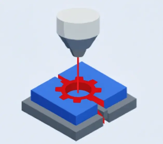
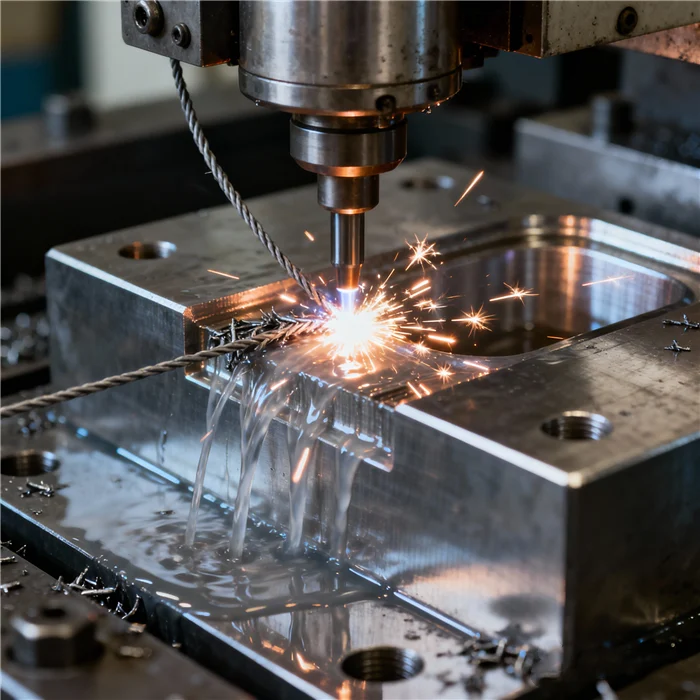
What is wire edm machining ?
Wire EDM (Electrical Discharge Machining) is a precision machining process that uses fine metal wire (usually copper or molybdenum) to create electrical sparks between the wire and the workpiece. The sparks melt or vaporize the material, enabling precise cutting. Wire EDM is widely used for machining complex shapes, high-precision parts, and hard materials in industries such as mold making, aerospace, and automotive. Its key advantages include no tool wear and high accuracy.
EDM is divided into fast wire, slow wire and medium wire EDM
Material for wire EDM machining
Wire EDM machining can process conductive materials with high hardness, complex shapes or that are difficult to process with traditional machining.
Material :
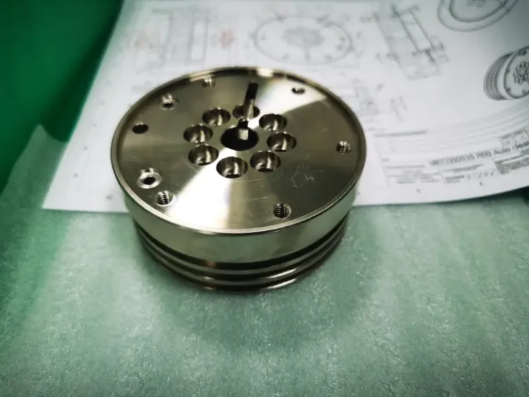
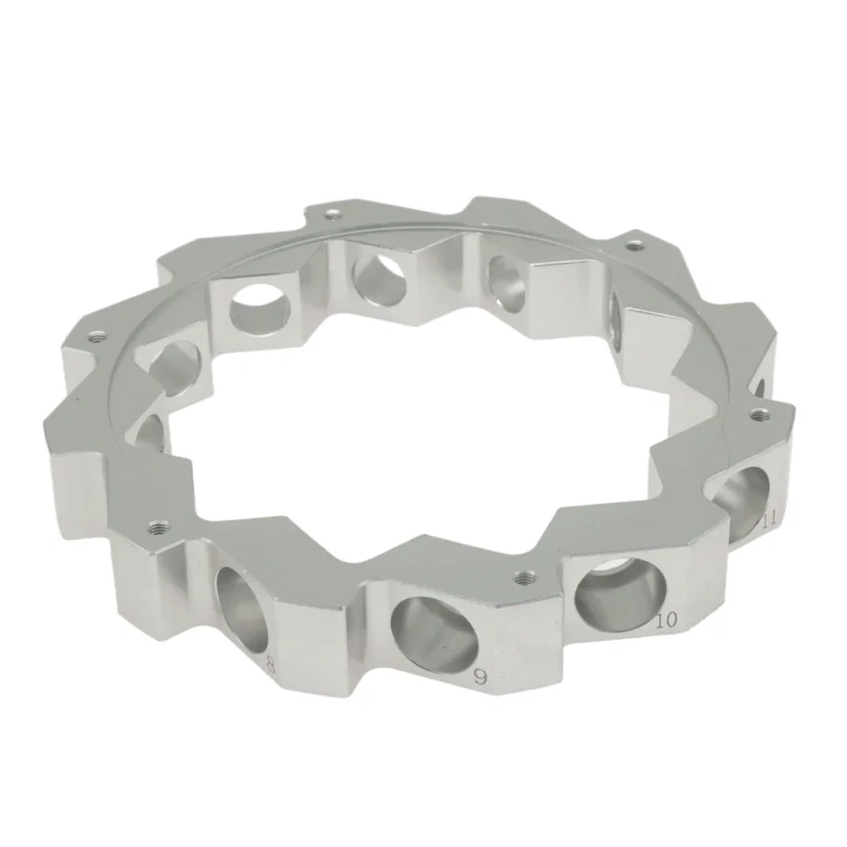
Aluminum
Aluminum is a widely used material for precision machining due to its low density, good strength, and corrosion resistance. commonly applied in aerospace, biomedical implants, and automotive parts.
Color : Silver.
Types : Aluminum 6061、7075、2024、5052、6063 and MIC-6.
Surface finish : Polishing, Brushing, Sandblasting, Chrome Plating, Anodizing, Electroplating, Powder Coating, Laser Etching.
Delivery time : 1-5 days.
")
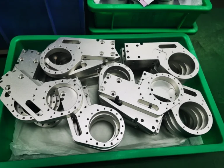
Stainless steel
Stainless steel provides excellent corrosion resistance and a smooth, easy-to-clean surface.widely used in kitchen equipment, medical devices, construction, and automotive parts.
Color : Silver.
Types : Stainless steel 304/316/201/202/430/444/410/420/440c/2205/2507/17-4ph/17-7ph.
Surface finish : Polishing, Brushing, Sandblasting, Electroplating, Spraying, PVD (Physical Vapor Deposition), Passivation, Pickling, Coloring.
Delivery time : 2-5 days.
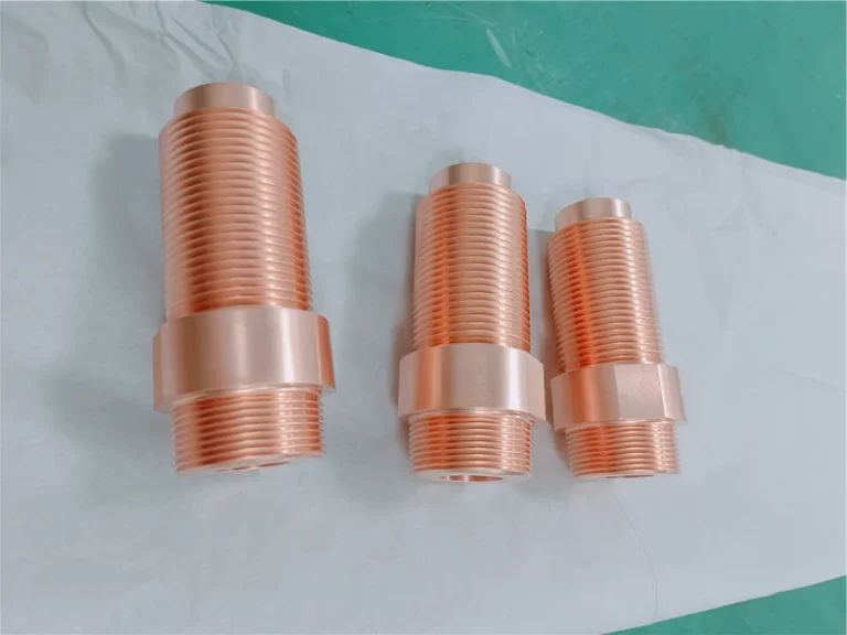
Copper
Possesses electrical conductivity, tensile ductility, and antimicrobial properties, primarily used for processing into crafts, decorative items, and medical equipment.
Color :Orange,yellow.
Types : copper H59/H62/Hpb59-1/C36000/HAI77-2/HSN62-1/HPb/HMn/HAl/HSn/HNi.
Surface finish : Passivation, Electroplating, Chemical Plating, Shot Peening, Sandblasting, Chemical Film Treatment, Polishing, Bright Cleaning.
Delivery time : 1-5 days.
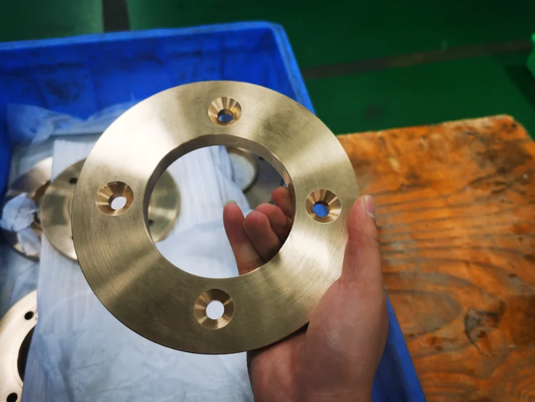
Bronze
Bronze is a copper–tin alloy (often with elements like lead or zinc) with a low melting point, good fluidity, and strong corrosion resistance.widely used for sculptures, bearings, gears, valves, and marine components such as propellers, hull fittings, and pumps.
Color : gold/brown.
Types : Tin bronze, aluminum bronze, beryllium bronze, silicon bronze, manganese bronze.
Surface finish : Sandblasting, polishing, knurling, grinding, passivation, chemical film coating, impregnation coloring, brush/spray coloring, electroplating, anodizing, powder coating, brushing.
Delivery time : 1-5 days.
Steel
Steel is an iron–carbon alloy with adjustable properties like strength, toughness, and corrosion resistance.
It is widely used for mechanical parts, cutting tools, and engine components.
Color : Silver .
Types : Steel S20C,S45C,S50C,SK85,SK95,40Cr,4140,4130,H13,D2,W1,A2,D2,M2,SKD11,ASP-23,S136.
Surface finish :Sandblasting, Mirror Finish, PVD Coating, Brushed Finish, Spray Coating, Electroplating.
Delivery time : 1-5 days
Magnesium
Magnesium has low density, low hardness, and good thermal conductivity. Its strength-to-weight ratio exceeds that of aluminum alloys and steel, and its excellent damping properties make it suitable for aerospace, automotive, and electronics applications.
Color : Silver.
Types : Magnesium alloy AZ91D/AM60B/AM50A/AS41B/ZK60/MB8/AZ31/WE43/ZE41/LA141/LZ91.
Surface finish : Chemical conversion coating, anodizing, nickel plating, electroplating, composite coating, spray painting, powder coating, electrophoretic coating.
Delivery time : 1-5 days.
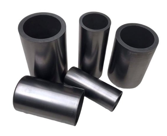
Graphite
Graphite conductivity is used for precision molding to avoid dust pollution caused by machining. It is mainly used for electrode manufacturing and EDM molds.
Color : Black.
Surface finish : Mechanical cutting, pickling, electrolytic treatment, coating, polishing, EDM surface strengthening.
Delivery time : 3-5 days
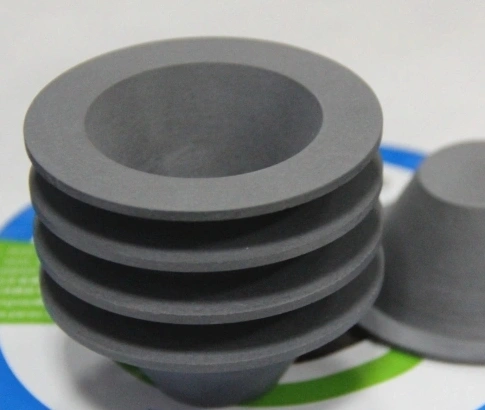
Conductive ceramic part
Conductive ceramics, used in aerospace and components like sensors and electronic parts, offer high hardness and chemical stability but are difficult to machine.
Pulsed discharge enables high-temperature, contactless processing, reducing stress and cracking.
Type : Oxide/non-oxide conductive ceramics, composite conductive ceramics
Color : white, gold, pink black, etc.
Delivery time : 3-5 days
Wire EDM machining advantage
High Precision: Achieves ultra-high accuracy up to ±0.001 mm, ideal for complex, high-tolerance parts.
No Physical Contact: Non-contact machining avoids tool wear and thermal deformation, suitable for various materials.
Machining Complex Shapes: Easily produces intricate geometries and fine details like small holes and narrow cuts.
Suitable for High-Hardness Materials: Capable of machining materials above 60 HRC, including carbide and titanium alloys.
No Mechanical Stress: Eliminates stress concentration, preserving part stability and accuracy.
High Surface Quality: Produces smooth surfaces with low roughness, reducing post-processing needs.
Long-Term Stable Operation: Supports continuous, stable machining for high-volume production.
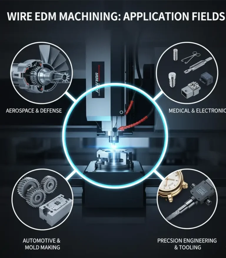
Application of wire EDM machining parts
Mold Manufacturing: Produces high-precision mold components like cavities, inserts, and cooling channels.
Aerospace: Machines complex, high-precision parts such as engine components, turbine blades, and gears.
Automotive: Manufactures precision automotive parts including engine components, cooling holes, and fuel nozzles.
Medical Devices: Used for high-precision surgical instruments and dental equipment with excellent surface finish.
Precision Machinery: Produces gears, bearings, and cutting tools with complex geometries and high accuracy.
Energy Industry: Creates high-strength, corrosion-resistant parts for nuclear and wind energy applications.
Metalworking & Art: Enables intricate engravings and decorative designs for jewelry and artistic work.
FAQ of wire EDM machining
What is the working principle of Wire EDM?
Wire EDM (Electrical Discharge Machining) cuts conductive materials by generating high-voltage electrical sparks between a thin metal wire (typically molybdenum or brass) and the workpiece. The instantaneous high temperature (up to several thousand degrees Celsius) melts and vaporizes the material, while deionized water flushes away the molten debris. The entire process is precisely controlled by a CNC system.
What accuracy can Wire EDM achieve?
Wire EDM typically achieves ±0.002-0.005mm accuracy with surface roughness below Ra0.8μm.
Advantages:
– Can cut narrow slots (0.05mm wide) and sharp internal corners (R0.1mm or less);
– High repeat positioning accuracy for mass production;
– Often requires no subsequent polishing.
Case: In aerospace, turbine blade cooling holes must be machined within ±0.003mm tolerance, making Wire EDM the only viable solution.
How does Wire EDM efficiency compare to milling?
Efficiency characteristics:
– Single-piece speed: Slower than milling (~50-200mm²/min), but ideal for complex shapes;
– Mass production advantage: Enables 24/7 unattended operation with automatic wire threading (AWT) and CNC programming;
– Material adaptability: More efficient than milling for hard materials (e.g., HRC60+).
Comparison with milling:
– Advantages: No cutting force (preventing workpiece deformation); can process ultra-hard materials;
– Disadvantages: Slower than milling; may form oxide layers requiring post-cleaning.
Does Wire EDM create oxide layers on surfaces? How to handle them?
Oxide layer causes: High-temperature sparks oxidize the surface, forming a 0.01-0.05mm thick black/gray layer.
Treatment methods:
– Mechanical removal: Sandpaper grinding, sandblasting;
– Chemical cleaning: Acid or alkaline washing;
– Electrochemical polishing: Improves surface finish.
Industry practice: For medical implants, oxide layers must be completely removed to ensure biocompatibility.
What safety risks exist in Wire EDM? How to prevent them?
Main risks:
– Electric shock: High-voltage sparks may cause electrocution;
– Mechanical injury: Wire breakage or workpiece ejection;
– Fire: Abnormal conductivity of deionized water or flammable oil-based coolants.
Prevention measures:
– Equipment protection: Install lightning protection and emergency stop buttons;
– Operation norms: Never touch the wire; keep electrical cabinets closed during processing;
– Environment control: Maintain dry work areas and regularly inspect coolants.
What factors affect Wire EDM costs?
Cost components:
– Equipment depreciation: High-end machines cost ~$70,000-$280,000;
– Consumables: Wire (~$70-$280 per roll), deionized water (requires regular replacement);
– Energy consumption: ~5-15kWh per hour of machining;
– Labor costs: Requires skilled programmers/operators.
Optimization suggestions:
– Mass production: Reduce manual intervention with CNC programming;
– Material selection: Prioritize highly conductive materials (e.g., copper) to shorten processing time;
– Process optimization: Use rough+finish two-step machining to balance efficiency and precision.