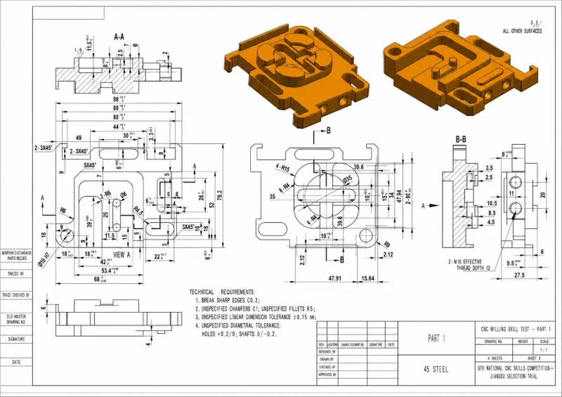
3-, 4- & 5-Axis Precision Machining
Custom CNC Milling Services for Precision Parts
Upload your drawing or 3D model for custom metal, plastic, composite and machinable-ceramic parts. We support prototypes, low-volume orders and repeat production with drawing-based inspection.
- Custom CNC-milled parts
- Tolerances down to ±0.002 in
- Prototype and batch production
- Critical dimensions inspected
Choose the Right CNC Milling Process
Select the axis configuration according to feature access, part geometry and setup requirements.

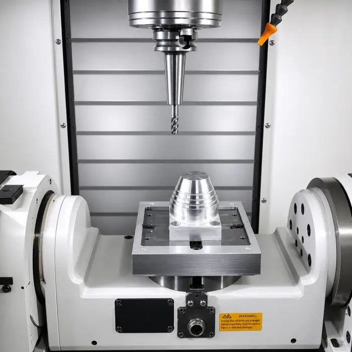
3-Axis CNC Milling
For plates, brackets, housings, pockets and features reached from one primary direction.
View 3-Axis Milling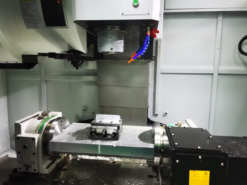
4-Axis CNC Milling
For cylindrical parts, side holes, slots and circumferential features with fewer reorientations.
View 4-Axis Milling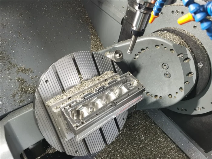
5-Axis CNC Milling
For compound angles and multi-face parts using 3+2 positioning or simultaneous five-axis motion.
View 5-Axis MillingCNC Milling Materials
Select metals or engineering plastics, then compare each material's characteristics, service environment, common parts, grades and finishing options.
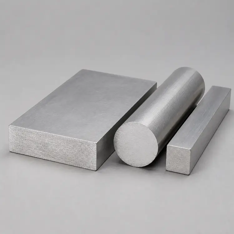
Aluminum
Lightweight, corrosion-resistant and highly machinable for complex geometry and efficient production.
- Service Environment
- Lightweight structures, thermal assemblies and protected outdoor equipment.
- Common Parts
- Housings, brackets, heat sinks, panels, fixtures and structural parts.
- Common Grades
- 6061-T6, 6082-T6, 5083, 7075-T6 and MIC-6.
- Surface Finishes
- Anodizing, chemical film, bead blasting, polishing and powder coating.
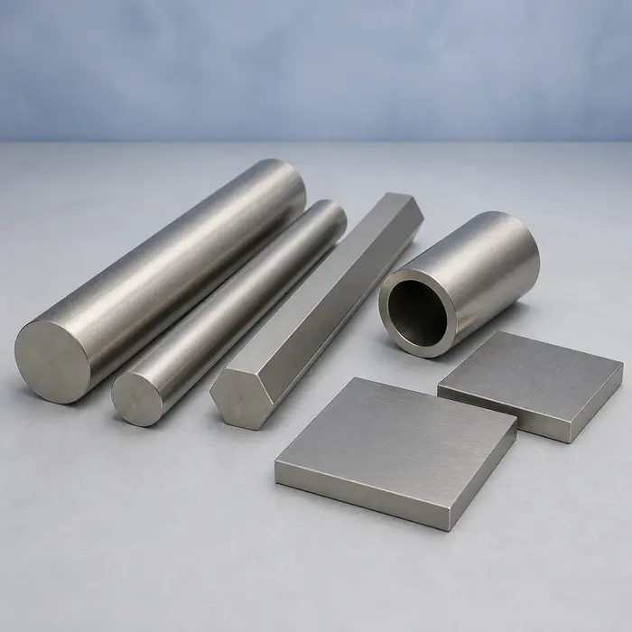
Stainless Steel
High strength, corrosion resistance and cleanability for demanding precision parts.
- Service Environment
- Food, medical, fluid-handling and corrosion-prone industrial service.
- Common Parts
- Valve bodies, fittings, manifolds, fixtures and instrument components.
- Common Grades
- 303, 304/304L, 316/316L, 17-4 PH and 420.
- Surface Finishes
- Passivation, electropolishing, bead blasting, brushing and PVD.
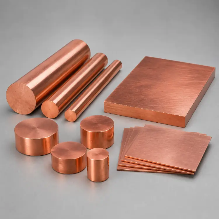
Copper
Excellent electrical and thermal conductivity with grade-dependent machinability and strength.
- Service Environment
- Electrical, thermal-management, vacuum and fluid-transfer systems.
- Common Parts
- Busbars, contacts, heat spreaders, electrodes and cooling plates.
- Common Grades
- C10100, C10200, C11000, C14500 and C17200.
- Surface Finishes
- Polishing, nickel or tin plating, passivation and clear coating.
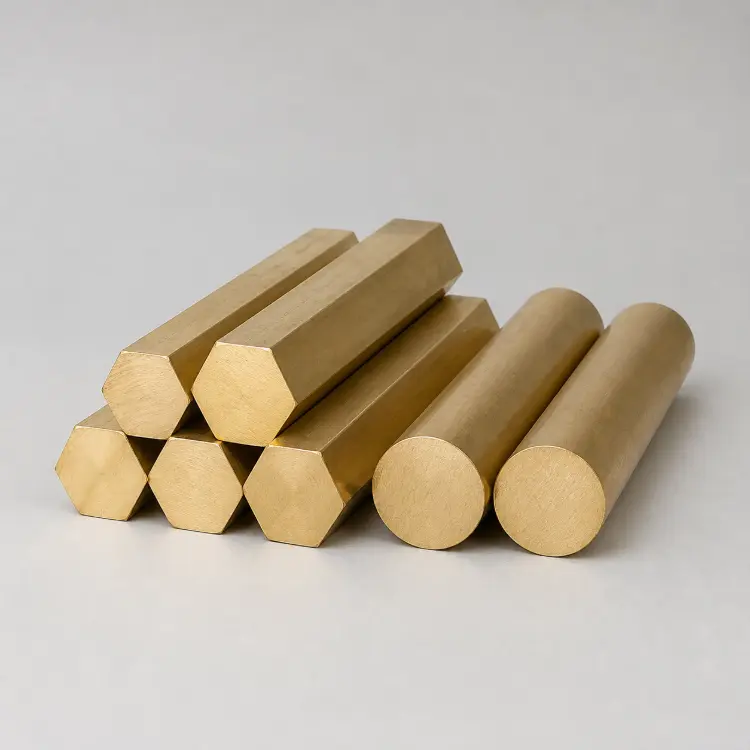
Brass
Good machinability, corrosion resistance and repeatability for precision hardware.
- Service Environment
- Plumbing, instrumentation, electrical and decorative assemblies.
- Common Parts
- Valves, fittings, inserts, terminals, gears and bushings.
- Common Grades
- C26000, C36000, C37700, C46400 and C69300.
- Surface Finishes
- Polishing, brushing, nickel or chrome plating and clear coating.
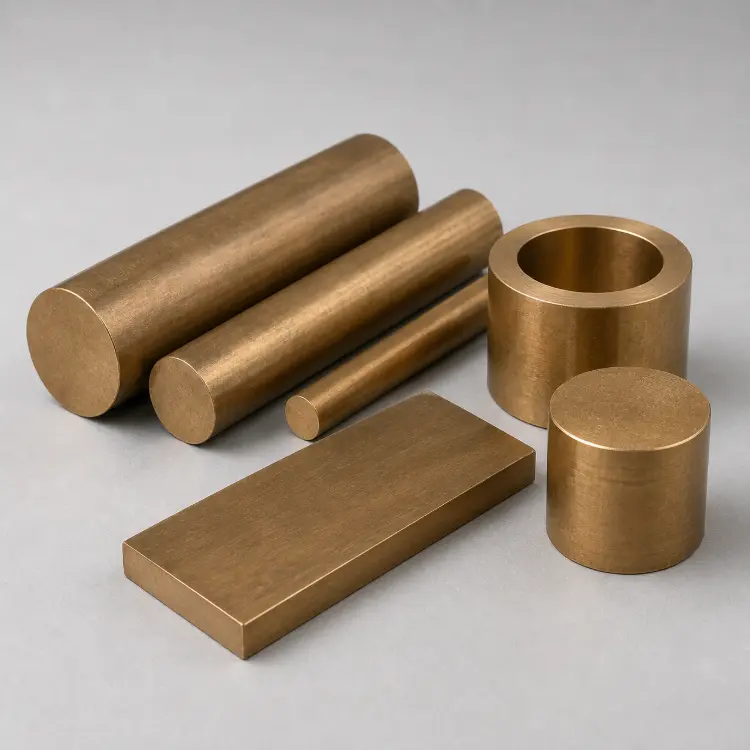
Bronze
Wear resistance, corrosion resistance and dependable sliding behavior for loaded parts.
- Service Environment
- Marine, pump, valve and heavy-duty sliding or rotating systems.
- Common Parts
- Bearings, bushings, gears, wear plates and valve parts.
- Common Grades
- C51000, C65500, C86300, C93200, C95400 and C95500.
- Surface Finishes
- Polishing, grinding, bead blasting, plating and patination.
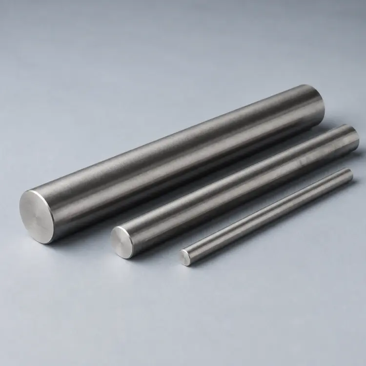
Steel
High stiffness, load capacity and heat-treatment flexibility for structural parts.
- Service Environment
- Heavy machinery, tooling and high-load protected assemblies.
- Common Parts
- Gears, shafts, tooling plates, fixtures and machine components.
- Common Grades
- A36, 1018, 1045, 4140, 4340 and A2.
- Surface Finishes
- Black oxide, plating, phosphating, powder coating and grinding.
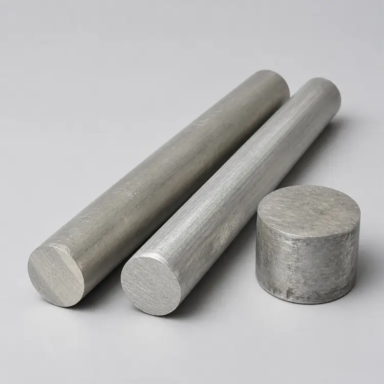
Magnesium
Very low density and good machinability for lightweight structural parts.
- Service Environment
- Aerospace, mobility and electronics where weight reduction is critical.
- Common Parts
- Housings, covers, brackets, frames and gearbox cases.
- Common Grades
- AZ31B, AZ61B, AZ80A, AZ91D, ZK60A and WE43.
- Surface Finishes
- Conversion coating, anodizing or PEO, plating and powder coating.
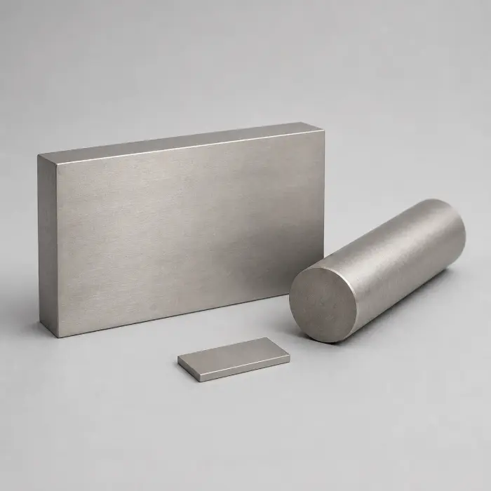
Titanium Alloy
High specific strength and corrosion resistance for demanding lightweight components.
- Service Environment
- Aerospace, medical, marine and chemical-service applications.
- Common Parts
- Brackets, implants, fasteners, valve parts and housings.
- Common Grades
- Grade 2, Grade 3, Grade 4, Grade 5 and Grade 23.
- Surface Finishes
- Anodizing, bead blasting, polishing, PVD and nitriding.
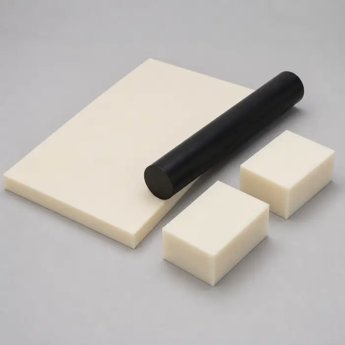
ABS
Balanced impact resistance, rigidity, machinability and cost for prototypes.
- Service Environment
- Indoor equipment and moderate-temperature service without prolonged UV.
- Common Parts
- Housings, covers, control panels, fixtures and brackets.
- Common Types
- General-purpose, high-impact, heat-resistant, flame-retardant and MABS.
- Surface Finishes
- Sanding, polishing, painting and validated vapor smoothing.
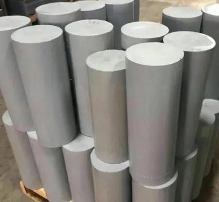
PVC
Chemical resistance, electrical insulation and low cost for fluid-system parts.
- Service Environment
- Chemical handling, water treatment and electrical insulation.
- Common Parts
- Flanges, valve parts, manifolds, spacers and panels.
- Common Types
- PVC-U, PVC-C, antistatic and flame-rated formulations.
- Surface Finishes
- As-machined, deburring, polishing, engraving and coating.
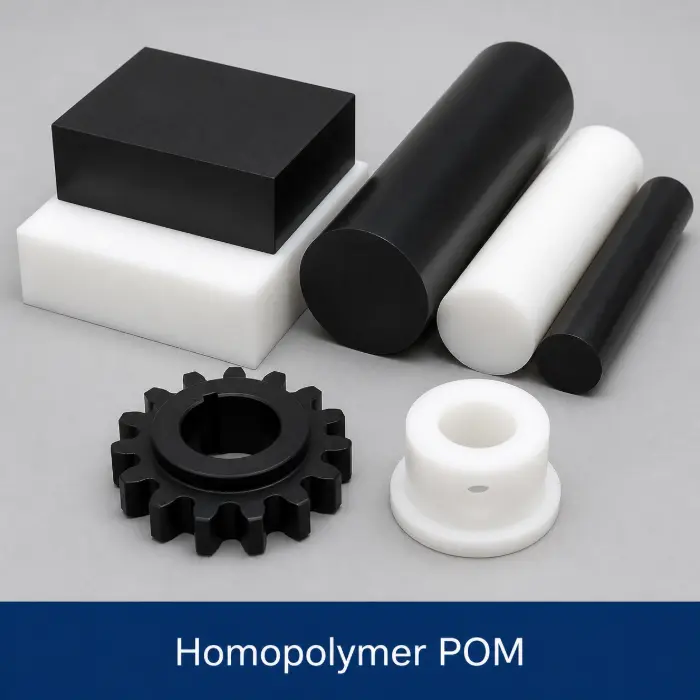
POM / Delrin
Low friction, wear resistance and dimensional control for precision mechanisms.
- Service Environment
- Sliding and rotating systems under moderate temperature and load.
- Common Parts
- Gears, bushings, rollers, guides and valve parts.
- Common Types
- POM-H, POM-C, glass-filled, PTFE-filled and antistatic grades.
- Surface Finishes
- Grinding, polishing, bead blasting and laser marking.
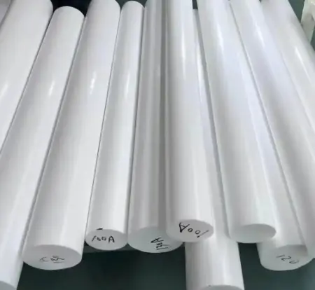
PTFE
Exceptional chemical resistance, low friction and electrical insulation.
- Service Environment
- Chemical processing, sealing, insulation and low-friction service.
- Common Parts
- Seals, gaskets, valve seats, insulators and guide rings.
- Common Types
- Virgin, glass-filled, carbon-filled, bronze-filled and modified PTFE.
- Surface Finishes
- Usually as-machined; bonding requires surface activation.
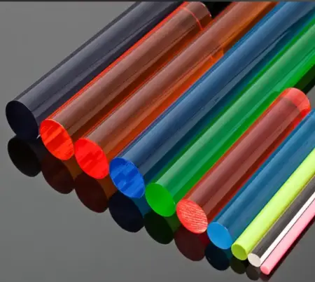
PMMA / Acrylic
Optical clarity, weather resistance and polishability for transparent parts.
- Service Environment
- Optical, lighting, display and laboratory applications.
- Common Parts
- Windows, lenses, light guides, covers and display blocks.
- Common Types
- Cast, extruded, optical, impact-modified and colored PMMA.
- Surface Finishes
- Mechanical, vapor or flame polishing, sanding and coating.
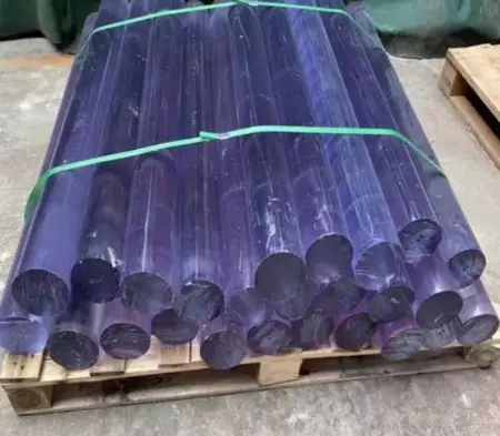
Polycarbonate / PC
High impact resistance, toughness and optional transparency for durable parts.
- Service Environment
- Guards, housings and impact-loaded protected assemblies.
- Common Parts
- Machine guards, lenses, covers, insulators and housings.
- Common Types
- Natural, optical, UV-stabilized, flame-retardant and glass-filled PC.
- Surface Finishes
- Polishing, vapor polishing, hard coating, painting and printing.
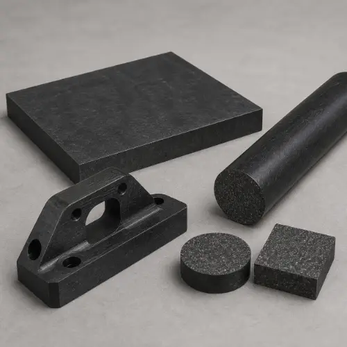
PA / Nylon
Tough, fatigue-resistant and wear-resistant, with moisture-sensitive dimensions.
- Service Environment
- Industrial motion, impact and wear with moisture allowances.
- Common Parts
- Gears, rollers, pulleys, guides, bushings and supports.
- Common Types
- PA6, PA66, PA12, cast PA6, lubricated and reinforced PA.
- Surface Finishes
- Grinding, polishing, bead blasting, dyeing and marking.
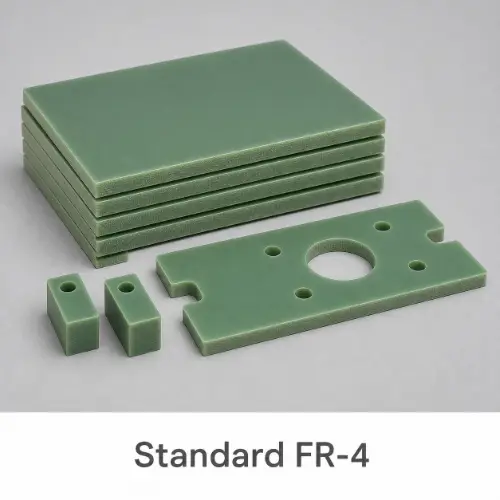
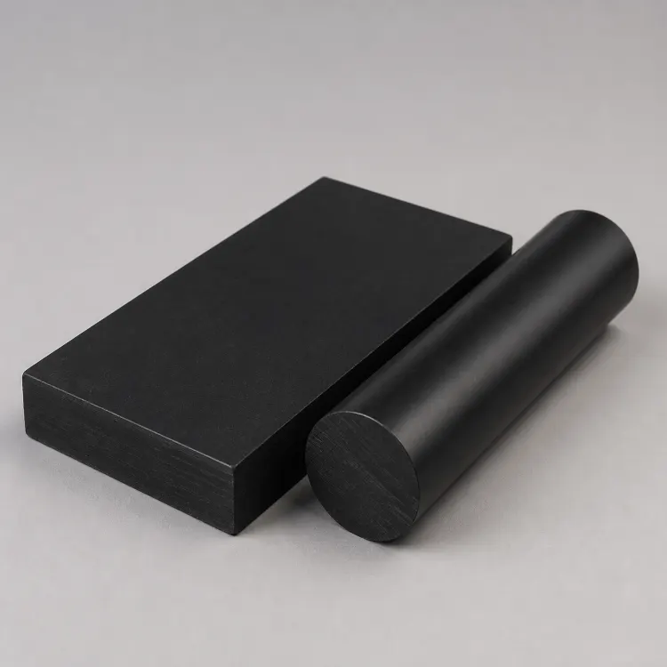
FR4
Rigid, electrically insulating and flame-retardant glass-epoxy laminate.
- Service Environment
- Electrical and test systems within the grade's thermal rating.
- Common Parts
- Insulation plates, fixtures, supports, spacers and terminal boards.
- Common Types
- Standard, mid-Tg, high-Tg, halogen-free, high-CTI and low-loss.
- Surface Finishes
- Edge sanding, grinding, edge sealing and printed marking.
Polyethylene / PE
Low density, chemical resistance and toughness for wear and fluid parts.
- Service Environment
- Wet, chemical, food-handling and low-temperature applications.
- Common Parts
- Guides, wear strips, tanks, spacers and valve parts.
- Common Types
- LDPE, MDPE, HDPE, UHMW-PE and filled grades.
- Surface Finishes
- Deburring, polishing, welding and activated printing or bonding.
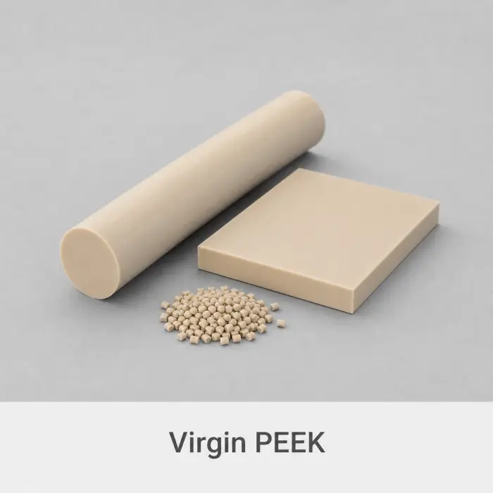
PEEK
Mechanical strength, chemical resistance and stability at elevated temperatures.
- Service Environment
- High-temperature, chemical, vacuum, medical and semiconductor service.
- Common Parts
- Valve seats, insulators, seals, fixtures and wear parts.
- Common Types
- Virgin, GF30, CF30, bearing-grade, ESD and medical grades.
- Surface Finishes
- Polishing, bead blasting, laser marking and plasma treatment.
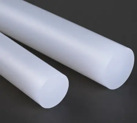
Polypropylene / PP
Low density, chemical resistance and fatigue performance for economical parts.
- Service Environment
- Chemical, laboratory, food-contact and wet-process equipment.
- Common Parts
- Tanks, covers, manifolds, guides, housings and spacers.
- Common Types
- PP-H, PP-B, PP-R, impact-modified and filled PP.
- Surface Finishes
- Deburring, polishing, welding and activated printing or bonding.
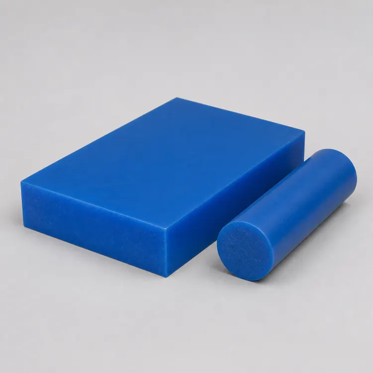
HDPE
High impact resistance, low moisture absorption and good chemical resistance.
- Service Environment
- Food, water-treatment, chemical and suitable outdoor systems.
- Common Parts
- Wear strips, cutting boards, valve bodies and conveyor parts.
- Common Types
- Natural, UV-stabilized, high-impact, antistatic and filled HDPE.
- Surface Finishes
- Deburring, polishing, welding and activated marking.
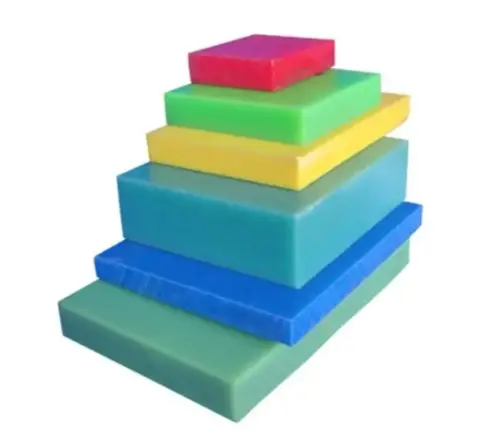
HIPS
Impact-modified polystyrene with easy machining and low moisture absorption.
- Service Environment
- Indoor appliance, display, packaging and moderate-load applications.
- Common Parts
- Housings, panels, covers, trays, templates and prototypes.
- Common Types
- General-purpose, high-impact, flame-retardant and reinforced HIPS.
- Surface Finishes
- Sanding, polishing, painting, printing and coating.
Final material, temper, filler, certification and finish are confirmed against the drawing, service conditions and supplier data sheet.
From CAD to Shipment
CNC Milling Process & Quality Control
Drawing requirements are reviewed before production and verified with suitable inspection equipment before shipment.
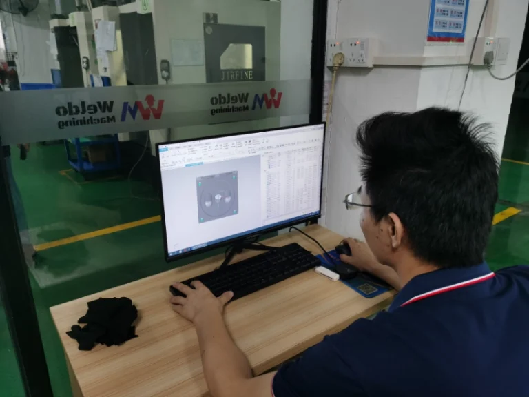
DFM & Programming
Review geometry, datums, tolerances and tool access before creating toolpaths.
Workpiece Setup
Prepare stock, fixtures, tools and machining coordinates.
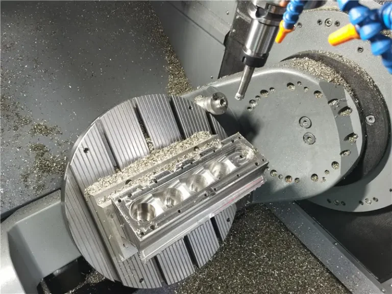
CNC Milling
Run the approved program with controlled tooling, cooling and in-process checks.
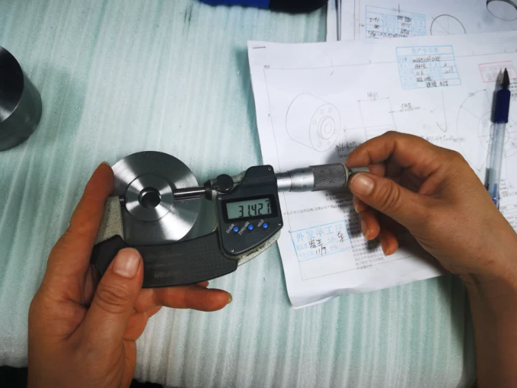
Inspection
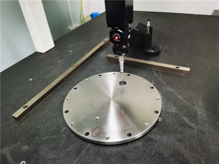
Verify critical dimensions with gauges, optical equipment or CMM.
Finish & Delivery
Complete approved post-processing, protection, labeling and packing.
Upload Your CNC Milling Drawings
Send the drawing, material, quantity, tolerances and finish requirements. Our engineers will review manufacturability and provide a clear production quote.
Upload Drawing for a Quote →