
CNC Turning Services
Custom CNC Turning Services
Precision-turned shafts, bushings, pins, sleeves, threaded parts and fittings in metals and engineering plastics. Upload your drawing for DFM review and a transparent quote—from prototype to repeat production.
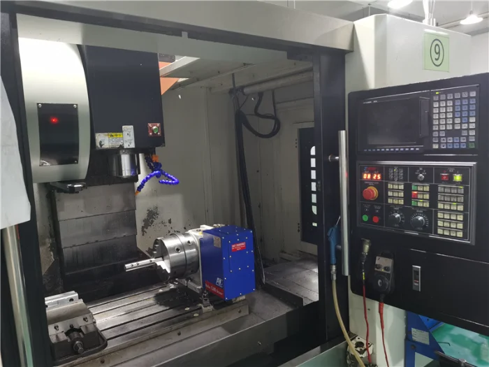
Turning Process
How CNC Turning Works
The workpiece rotates while programmed tools create controlled diameters, bores, grooves, tapers and threads.
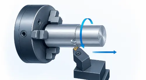
Setup and Datum
Stock, grip length, runout and reference faces are established.
Rough Turning
Material is removed while controlling cutting force, heat and chip formation.
Finish Features
Critical diameters, bores, grooves and threads are completed to the drawing.
Inspection
Dimensions, runout, threads and surface finish are verified before release.
For parts combining rotational and prismatic features, our CNC machining capabilities coordinate turning, milling, drilling and secondary operations within one production route.
Turning Capability
CNC Turning Parameters
Use these values for early design planning. Final capability is confirmed from the material, geometry, clamping method and inspection plan.
| Capability | Parameter |
|---|---|
| Maximum Work Envelope | Up to Ø500 × 1200 mm |
| Minimum Diameter | From Ø1 mm |
| Typical Turned Finish | Ra 0.8–3.2 μm |
| Recommended Metal Wall | From approximately 0.7 mm |
| Recommended Plastic Wall | From approximately 1.5 mm |
| Thread Range | Internal and external threads, M1–M50 |
| Preferred Deep-Hole Ratio | Up to 5× diameter; deeper features require review |
| Production Volume | Prototype, low-volume and repeat production |
Drawing-Based Tolerances
CNC Turning General Tolerances
When ISO 2768-1 is stated on the drawing, these general linear tolerances apply only to dimensions without an individual tolerance indication.
| Nominal Dimension | Fine — ISO 2768-f | Medium — ISO 2768-m |
|---|---|---|
| 0.5–3 mm | ±0.05 mm | ±0.10 mm |
| Over 3–6 mm | ±0.05 mm | ±0.10 mm |
| Over 6–30 mm | ±0.10 mm | ±0.20 mm |
| Over 30–120 mm | ±0.15 mm | ±0.30 mm |
| Over 120–400 mm | ±0.20 mm | ±0.50 mm |
| Over 400–1000 mm | ±0.30 mm | ±0.80 mm |
| Over 1000–2000 mm | ±0.50 mm | ±1.20 mm |
ISO 2768 applies only when invoked on the drawing. Fits, threads, runout, concentricity, surface finish and dimensions below 0.5 mm require individual specifications.
Turning Materials
Materials for CNC-Turned Parts
Material selection is based on load, wear, corrosion, temperature, friction and dimensional stability.
Aluminum
Lightweight shafts, spacers, housings and fittings in commonly machined aluminum grades.
Stainless Steel
Valve parts, threaded rods, fittings and corrosion-resistant precision sleeves.
Carbon and Alloy Steel
Rollers, pins, couplings and load-bearing transmission shafts.
Brass and Bronze
Fittings, bushings, bearings, connectors and precision instrument components.
Copper
Electrical contacts, terminals, cooling components and conductive fittings.
Engineering Plastics
POM, PEEK, PTFE, nylon and PE for low-friction, insulating or chemical-service parts.
Specify the exact grade, condition, temper or filler when requesting a quotation. Material traceability and supporting records are available when required.
Design for Turning
Reduce CNC Turning Cost at the Drawing Stage
Simple geometry and clearly defined functional requirements reduce setup, tooling and inspection time.
Use Standard Stock
Match the main diameter to available bar or tube sizes to reduce material removal.
Control Slender Features
Shorter unsupported lengths reduce deflection, chatter and additional support requirements.
Limit Tight Tolerances
Apply precision requirements only to functional fits, datums and critical interfaces.
Use Standard Threads
Standard thread sizes and practical tool-relief grooves reduce special tooling.
Turned Part Projects
Custom CNC-Turned Parts
Precision metal and plastic components from prototypes to repeat production.
Production and Inspection
From Drawing Review to Final Inspection
Critical turning features are identified before production and verified before shipment.
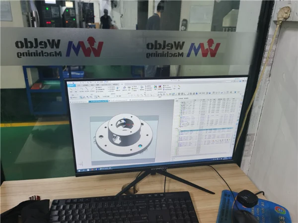
Drawing Review
Check material, wall thickness, threads, reliefs, runout and clamping risks.
Controlled Production
Turning, secondary machining and inspection follow the approved route.
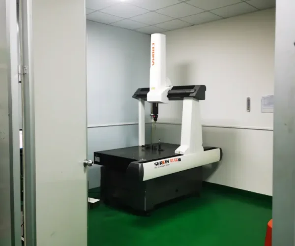
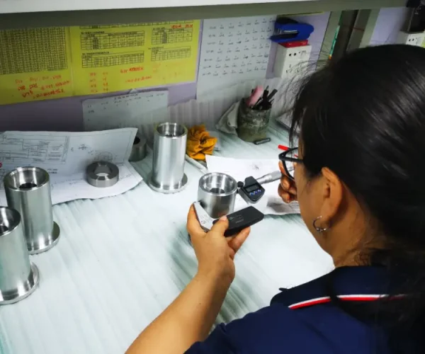
Dimensional Inspection
Critical diameters, bores, runout and threads are verified with suitable equipment.

Delivery Control
Approved parts are cleaned, protected, labeled and packed for shipment.
Heat treatment, precision grinding and surface finish requirements can be coordinated with the machining and inspection plan.
CNC Turning FAQ
Plan Your CNC Turning Project
What is the difference between CNC turning and CNC milling?
Turning rotates the workpiece and is suited to round geometry. Milling moves a rotating tool across a stationary part to create faces, pockets and complex contours.
Can turned parts include flats, slots or cross holes?
Yes. Live tooling or a controlled secondary milling setup can add non-rotational features when tool access and datum control permit.
How are long, slender turned parts controlled?
Tailstocks, steady rests, staged machining, lower cutting forces and runout inspection help control vibration and deflection.
How can CNC turning costs be reduced?
Use standard stock, limit tight tolerances to functional features, specify standard threads and reduce unnecessary setups.
What affects CNC turning lead time?
Material availability, geometry, quantity, tolerance, heat treatment, finishing and inspection requirements determine the schedule.