In the field of precision manufacturing, CNC milling parts are structural components produced by removing material through CNC milling machines following pre-set programs. Their precision and reliability directly determine the performance of end products. From core components in aerospace to micro-components in electronic devices, precision-machined parts are ubiquitous across every industry. This article covers the entire CNC machining process, materials, precision, and industry applications, aiming to highlight its vital role in modern manufacturing.
The Complete CNC Milling Part Manufacturing Process
Precision machining requires coordinated multi-stage operations, with strict control at each step to ensure final products meet design specifications:
Design Phase
Engineers use CAD software like SolidWorks or AutoCAD to create 3D models or 2D engineering drawings, annotating critical parameters—such as external dimensions, hole diameters, wall thicknesses, surface roughness (e.g., Ra 0.8-3.2μm), and dimensional tolerances (e.g., ±0.005-±0.02mm).
Programming Phase
CAD models are imported into CAM software like Mastercam or UG. Machining parameters are set based on material properties and structural characteristics: selecting appropriate tools (e.g., high-speed steel end mills for aluminum alloys, carbide ball-nose cutters for titanium alloys), determine spindle speed (5000-20000 rpm), feed rate (30-200 mm/min), and cutting depth (0.1-5 mm). This process generates G and M codes to control tool movements and the motion path of the CNC milling base.
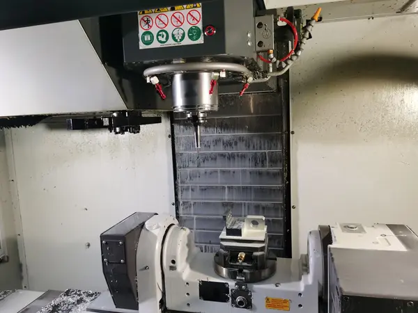
Clamping and Machining
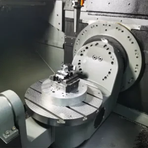
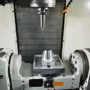
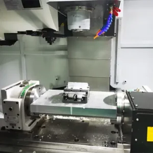
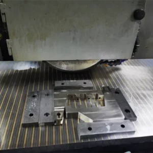
Select a vise, specialized fixture, or vacuum chuck to secure the workpiece on the milling machine table based on its size and shape. Use a tool presetter to calibrate the relative position between the tool and workpiece, ensuring precise X/Y/Z axis origin points. After starting the machine, the CNC spindle and tool head automatically perform cutting operations according to the program. Real-time monitoring of the cutting status is required to prevent dimensional inaccuracies caused by chip buildup or tool wear.
Inspection and Correction
Upon completion of machining, inspect the part’s dimensions and surface quality using tools such as digital calipers, micrometers, and coordinate measuring machines (CMMs). If deviations are detected, trace back to the design or programming stage. Adjust parameters (replace cutting tools) and re-machine to form a closed-loop process of “Design – Machining – Inspection – Correction,” ensuring every component meets specifications.
Material Compatibility for CNC-Milled Parts
The physical properties of different materials directly impact CNC machining efficiency and finished product quality. Tailored machining strategies must be developed:
Metal Materials
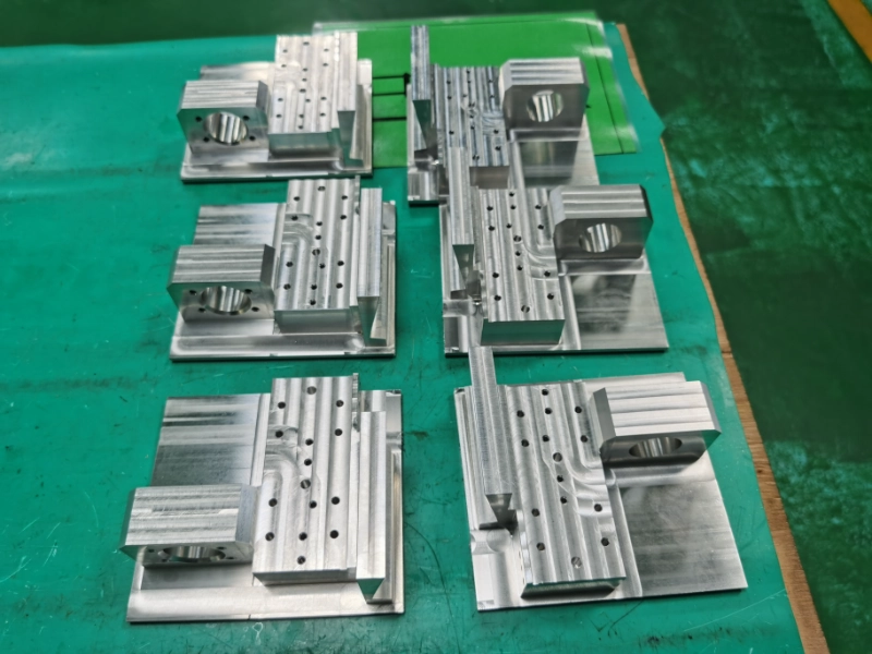
Aluminum Alloy (6061, 7075): Lightweight, relatively soft texture, excellent thermal conductivity. Commonly used in electronic 3C components such as smartphone frames and laptop heat sinks. During machining, use end mills with diameters ranging from 1-10mm at spindle speeds of 3000-10000 rpm. Employ cutting fluid for cooling to minimize tool wear and ensure smooth milled surfaces.
Stainless Steel (304, 316): Highly corrosion-resistant and hard, suitable for CNC-milled parts in medical devices and chemical equipment, such as surgical instrument blades and valve chambers. Use carbide tools with reduced feed rates (30-80 mm/min). Employ high-pressure cutting fluid to dissipate excess heat, preventing dimensional deviations from thermal deformation and extending tool life.
Titanium Alloys (TC4, TA15): High strength and heat resistance make these core materials for aerospace components like turbine blades and aircraft frames. Utilize 5-axis CNC milling machines with ultra-fine-grain carbide tools, maintaining cutting temperatures below 300°C to prevent material hardening that compromises machining accuracy.
Non-metallic Materials
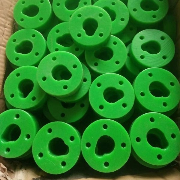
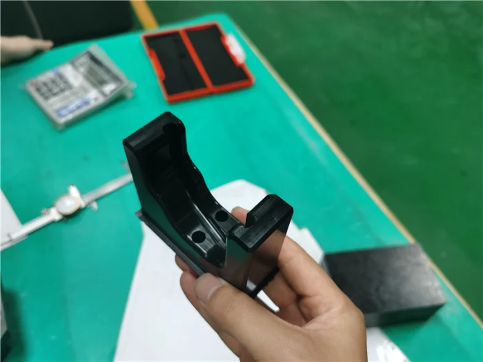
Engineering Plastics (ABS, PC): Excellent toughness and low cost, suitable for home appliances and automotive interiors like dashboard brackets and printer housings. High-speed steel tools suffice for machining at spindle speeds of 10,000-18,000 rpm. Use compressed air chip removal to prevent chip adhesion causing surface roughness.
Composite Materials (Carbon Fiber Reinforced Plastics, Glass Fiber Reinforced Plastics): High strength and fatigue resistance, used for milled parts in high-end equipment like drone bodies and racing components. Requires diamond-coated tools with feed rates controlled at 20-50 mm/min. Use air cooling instead of coolant to prevent moisture absorption and deformation, ensuring structural integrity.
Surface finish for cnc machining part
We offer a variety of surface treatment options for milled parts. Before surface treatment, we allow for the corresponding processing margin to ensure that the dimensional accuracy of the parts meets customer requirements after treatment. After treatment, our specialists will use dial gauges, micrometers, calipers, or coordinate measuring machines to measure difficult-to-measure holes, grooves, and curved surfaces, generating a comprehensive inspection report. Only parts that pass inspection will be packaged and shipped. Click to learn about our commonly used surface treatment methods.
Precision Control for CNC Milling Parts
High precision is the core competitiveness of milled parts, requiring a dual approach of equipment selection and process optimization to minimize errors:
Selecting Suitable CNC Machines
Standard 3-axis milling machines suit simple structures like flat surfaces and straight slots, with positioning accuracy of ±0.01mm. For complex curved surfaces—such as mold cavities or impellers—4-axis/5-axis machining centers are required. These offer repeat positioning accuracy of ±0.001mm and should incorporate electric spindles to enhance high-speed stability, minimizing vibration-induced precision loss.
Process Optimization: Minimizing Machining Errors
Layered Cutting: When machining deep grooves or thick-walled parts, avoid excessive single-pass depths that cause material waste. Adopt a “multiple small passes” approach (e.g., 0.3-0.5mm per pass) to prevent tool deformation and dimensional deviations.
Tool Compensation: Configure “tool radius compensation” and “length compensation” in the CNC system to offset errors from tool wear. For example, after milling 100 CNC machined parts, if a cutter’s edge wears by 0.002mm, compensation parameters can be adjusted to ensure subsequent parts still meet dimensional requirements.
Real-time Inspection: Some high-end equipment features probe inspection systems that automatically measure critical dimensions (e.g., hole diameter, wall thickness) during machining. Upon detecting deviations, the system dynamically adjusts parameters without requiring manual intervention or downtime, enhancing part consistency in batch production.

Industry Applications of CNC milling Parts
Leveraging high precision and flexibility, CNC-milled parts are widely adopted across multiple sectors, driving component manufacturing upgrades in other industries:
Automotive Manufacturing
Engine blocks and cylinder heads are typical milled components requiring multiple high-precision oil and water passages (hole tolerance ±0.02mm). Mass production is achieved using CNC high-speed horizontal machining centers, with individual machines capable of processing 50-100 parts daily. Battery pack frames for new energy vehicles (high-precision aluminum alloy components) require milling thin-walled structures (wall thickness 1.5-2mm). Through lightweight design and low-speed cutting, they ensure the sealing integrity and safety of battery installations.
Electronics & 3C
Mobile phone mid-frames, tablet casings, etc., featuring small dimensions (width 5-10mm) and dense hole patterns. Requires micro end mills with diameters of 0.5-2mm, processed using high-speed spindles at 15,000-20,000 rpm. Surface roughness controlled within Ra 0.8μm to ensure aesthetic quality. Micro-cavities in chip carriers (depth 0.1-0.5mm) require micro-milling processes with positioning accuracy of ±0.003mm to prevent damage to the chip mounting surface.
Medical Devices
Artificial joints (titanium alloy CNC-milled parts) require milling of ergonomic curved surfaces with a surface roughness of Ra 0.4μm to minimize tissue friction. Surgical scissors blades (stainless steel CNC parts) demand blade edge tolerances of ±0.005mm with zero burrs to prevent tissue damage during procedures. The entire manufacturing process must comply with medical GMP standards to ensure surface finish and biocompatibility of milled components.

Cost Control for CNC Milling Parts: Balancing Precision and Efficiency
Under the premise of quality assurance, rational cost control is pivotal in CNC milling production:
Optimizing Machining Parameters
Adjust spindle speed and feed rate based on part material and structure to reduce individual processing time without compromising precision. For example, when machining aluminum alloy, increasing spindle speed from 8000 rpm to 12000 rpm and feed rate from 50 mm/min to 80 mm/min can boost processing efficiency by 30%, lowering unit time costs.
Tool Management: Reduce Consumable Costs
Select cost-effective tools for different machining needs: use high-speed steel tools for standard plastic parts and carbide tools for hard metals. Extend tool life through optimized cutting parameters. For instance, a carbide milling cutter processing 500 stainless steel parts can reach 600 pieces with improved cooling, reducing replacement frequency.
Bulk Production
For parts with stable demand, adopt batch production to reduce setup cycles and machine debugging time. For instance, an electronics manufacturer cut single-part setup time from 5 to 2 minutes by batch-producing precision mobile phone frame components, lowering fixed costs by 40%.
Summary of cnc milling parts
CNC milled parts, characterized by high precision, flexibility, and broad adaptability, serve as core components in aerospace, automotive, electronics, and medical industries. From parameter annotation during design to precision control in machining, and industry-specific application adaptation, each step must align with the part’s performance requirements and operational environment. As manufacturing evolves toward “high precision, customization, and sustainability,” CNC milling will further optimize processing techniques, enhance quality and efficiency, provide stronger support for manufacturing upgrades across industries, and continue playing a pivotal role in the modern industrial ecosystem.
If you have a CNC milling part that requires prototyping, please contact us WELDO to get pricing for your design and prototyping. We will quickly provide a quote based on your material and the complexity of the process.