Introduction: Why Has Centerless Grinding Process Become a Core Process in Modern Manufacturing?
In high-precision fields such as aerospace, automotive manufacturing, and medical equipment, workpiece surface quality and dimensional tolerances directly impact product performance. Traditional center grinding requires workpieces to be clamped using centers or chucks, leading to issues like low clamping efficiency and insufficient rigidity. Centerless grinding, however, has emerged as the preferred solution for high-volume precision machining due to its characteristics of centerless positioning, continuous processing, and high-rigidity support. Industry data indicates that automotive component production lines utilizing centerless grinding achieve a 40% efficiency increase over traditional methods, with roundness errors controlled within 0.002mm.
Principles of Centerless Grinding Process
Core Components and Motion Mechanisms of Centerless Grinding
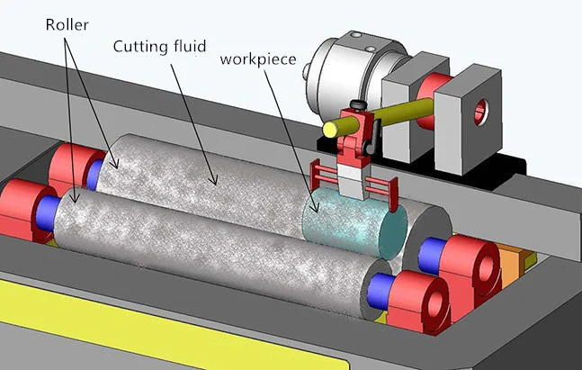
Centerless grinding achieves machining through three core components: the grinding wheel, guide wheel, and support plate:
Grinding Wheel: Rotates at high speed (linear velocity 60-140 m/s), performing material removal. Grit selection directly impacts surface quality (coarse grit for rapid stock removal, fine grit for mirror finish). .
Guide Wheel: Rotates at low speed (5-300 rpm), providing friction through rubber bonding agents to drive workpiece rotation. Its axis tilts 1°-5° to enable axial feed.
Support Plate: Bases the workpiece bottom, ensuring machining stability—particularly suited for slender shaft components.
Motion Synergy: The guide wheel rotates the workpiece, the grinding wheel cuts into the surface at higher speed, and the support plate limits radial runout, forming a dynamic equilibrium system. For instance, when machining hydraulic valve stems, precisely controlling the guide wheel tilt angle to 0.5° achieves axial dimensional accuracy of 0.001mm.
Process Classification and Applications of Centerless Grinding Process
Through-Feed Grinding:
The workpiece continuously passes through the gap between the grinding wheel and guide wheel. Suitable for cylindrical parts with a length-to-diameter ratio >5 (e.g., piston pins, shafts). An automotive manufacturer adopted this process for transmission shafts, reducing single-piece processing time to 8 seconds and increasing annual production capacity by 1.2 million units.
In-Feed Grinding:
The guide wheel is parallel to the grinding wheel axis. After radial positioning of the workpiece, localized grinding is performed. This method is suitable for stepped shafts and irregularly shaped components (e.g., gear shafts, camshafts). When machining new energy vehicle motor shafts, the in-feed process simultaneously controls bearing seat roundness ≤0.0015mm and shaft extension taper ≤0.003mm.
Face Feed Grinding:
Achieves face machining through axial movement of the guide wheel, commonly used for flanged sleeve-type components.
Historical Evolution of Centerless Grinding Process
1853: Schleicher developed the first centerless grinder for needle processing.
1915: Heim introduced the worktable plate and regulating wheel, significantly enhancing machining accuracy and application scope.
1960s-1970s: Rowe’s team laid the theoretical foundation through vibration analysis and roundness optimization research.
Modern Technical Enhancements
High-rigidity machine design: Utilizing hydrostatic guides and linear motor drives elevates the first resonance frequency to 500Hz, effectively suppressing forced vibrations.
Dynamic stability control: Real-time monitoring of acoustic emission signals via FFT and wavelet analysis correlates surface roughness (Rz), cylindricity, and roundness errors.
Process Advantages of Centerless Grinding Process
Significantly Enhanced Production Efficiency
Continuous Processing: Eliminating the clamping-machining-unclamping cycle. After adopting a through-feed centerless grinder, a bearing manufacturer increased daily single-line output from 5,000 to 12,000 units.
Multi-wheel integration: High-end models feature dual-wheel systems enabling simultaneous rough and finish grinding. For instance, Japan’s NANOFACTOR NVG-200A vertical grinder achieves a Ra 0.01μm mirror finish in a single setup.
Automated loading/unloading: Integrated cantilever hoppers and robotic arms reduce changeover time to 2 seconds, meeting Industry 4.0 requirements.
Superior precision control
Roundness Error Control: Optimized guide wheel inclination and grinding wheel dressing parameters reduce roundness error from 0.005mm in traditional processes to below 0.002mm.
Surface Quality Enhancement: Fine-grit grinding wheels (e.g., #2000 grit) combined with kerosene coolant achieve ultra-smooth surfaces with Ra 0.05μm, meeting stringent requirements for semiconductor equipment components.
Thermal Deformation Suppression: Utilizing a natural granite bed and water-cooled spindle maintains temperature fluctuations within ±0.5℃ in the machining zone, effectively preventing dimensional deviations caused by thermal deformation of metal rods during grinding.
Significant Cost-Effectiveness Optimization
Reduced Clamping Costs: Eliminating fixtures like centers and chucks lowers per-piece clamping costs by 60%.
Extended Grinding Wheel Life: The dual-support structure grinding wheel head reduces vibration, decreasing wheel consumption by 35%.
Defect Rate Control: An automated inspection system monitors machining parameters in real time, reducing the defect rate from 2% to below 0.3%.
Industry Applications of Centerless Grinding Process
Automotive Industry
Engine Crankshafts: Employing plunge-type centerless grinding ensures coaxiality between main journals and connecting rod journals ≤0.005mm, with an annual processing capacity exceeding 5 million units.
Drive Shafts: Through-feed grinding achieves linearity control of 0.02mm, supporting new energy vehicles’ high-speed requirements of 8000rpm.
Hydraulic Valve Bodies: Face-feed grinding guarantees sealing surface flatness ≤0.003mm, reducing leakage rates by 90%.
Aerospace
Turboshafts: Diamond grinding wheels and low-temperature cooling systems achieve Ra 0.1μm surface quality on HRC65 hardened super-hard alloy materials.
Fuel Injectors: Micro-orifices (Φ0.2mm) are machined on specialized centerless grinders, controlling flow deviation within ±1%.
Medical Devices
Biocompatible Materials
Artificial Joints: Centerless grinding achieves 0.001mm sphericity control in titanium alloy femoral heads, meeting ISO 13485 medical standards.
Surgical Instruments: Stainless steel handles polished with fine-grain wheels attain Grade A surface roughness, reducing bacterial adhesion risk.
Challenges and Solutions in Centerless Grinding Process
Common Defects and Root Causes
Ellipticity Error: Excessive guide wheel tilt angle causes periodic workpiece chatter. Solution: Optimize angle to 1.5°–3°.
Surface Burn: Resulting from excessive wheel linear speed or inadequate cooling. Solution: Control Vc ≤ 120 m/s and implement high-pressure cooling systems.
Dimensional Fluctuation: Support instability due to worn support plates. Solution: Replace plates every 2000 hours and implement online detection compensation.
Intelligent Upgrade Pathways
AI Parameter Optimization: Machine learning analyzes historical data to automatically adjust grinding wheel speed, feed rate, and other parameters. Our Weldo machining center achieved a 40% improvement in machining stability after implementation.
Digital Simulation Technology: Constructing virtual grinding machine models enables pre-simulation of machining processes, reducing trial production cycles by 70%.
Adaptive Control: Integrating force sensors with vision systems enables real-time correction of machining deviations, achieving “one-button” stable production.
Future Trends in Centerless Grinding Process
Technological Breakthrough Directions
Ultra-High-Speed Grinding: Achieving grinding wheel linear speeds exceeding 200 m/s, tripling material removal rates, suitable for difficult-to-machine materials like ceramics and cemented carbides.
Ultra-Precision Forming: Direct machining of non-circular cross-sections (e.g., polygonal shafts, elliptical holes) via form grinding wheel dressing technology to meet complex requirements for robotic joints.
Green Cooling Technology: Development of nanofluid coolants reducing cutting fluid consumption by 90% and minimizing environmental pollution.
Market Demand Drivers
New Energy Vehicles: Surging demand for precision machining of components like motor shafts and reducer gears, with the market projected to reach 12 billion yuan by 2025.
5G Communications: Surface flatness requirements of Ra ≤ 0.03μm for copper foil in high-frequency substrates drive centerless grinding toward micron-level precision.
Semiconductor Equipment: Wafer transport shafts demand nanometer-level cleanliness, spurring development of ultra-clean grinding machines.
Conclusion: Centerless Grinding Process—A Vital Engine for Precision Manufacturing
From traditional machining to smart factories, centerless grinding continuously propels manufacturing toward higher levels through its efficiency, precision, and flexibility. As materials science, artificial intelligence, and green technologies deepen their integration, this classic process will revitalize itself, providing core momentum for global industrial upgrading. For manufacturers, mastering centerless grinding technology is key to enhancing competitiveness.