
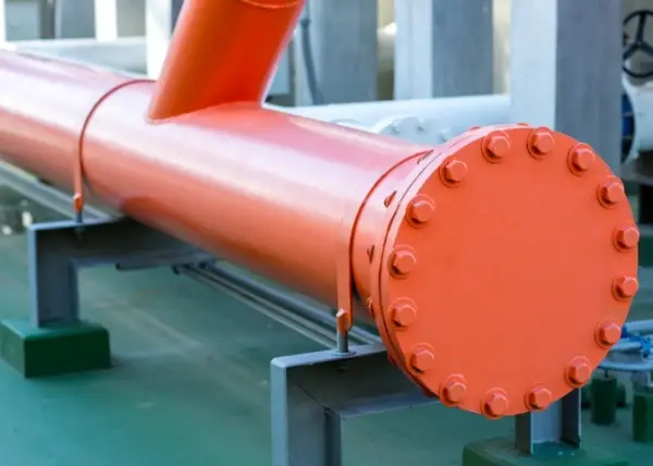
Dans les secteurs du pétrole et du gaz, de la pétrochimie, de l'énergie, de l'offshore et de la tuyauterie de process en général, une bride aveugle est l'un des composants de l'enveloppe de pression les plus simples d'apparence, mais les plus critiques en termes de sécurité. Il ne transporte pas de flux, mais il définit si votre système peut atteindre un véritable isolement positif et un contrôle d'arrêt fiable.
Lorsqu'il s'agit de terminer une ligne, d'isoler un équipement à des fins de maintenance ou d'effectuer des essais hydro/pneumatiques, une bride aveugle est souvent la solution la plus adaptée. une solution plus vérifiable et plus fiable que celle qui consiste à se fier uniquement aux soupapes.
Définition et conditions d'utilisation
A Bride aveugle est un bride solide sans alésage central. Il est boulonné à l'extrémité d'un tuyau ou d'une buse d'équipement à l'aide d'un joint, formant ainsi un ensemble complet. limite de pression que bloque complètement la voie d'écoulement.
Utilisation d'une bride aveugle
Les brides aveugles sont généralement spécifiées dans les cas suivants
- Terminaison de ligne est nécessaire à l'extrémité d'une canalisation ou d'une buse de rechange.
- Isolement positif est obligatoire pour les produits toxiques, inflammables ou dangereux.
- Limites de l'essai hydrostatique / de l'essai pneumatique doit être créé pour la vérification de l'intégrité du système.
- Maintenance en cas d'arrêt et de retournement nécessitent une barrière mécanique visible et fiable.
- Redondance est souhaitable en aval des vannes pour réduire le risque de fuite.
Types de brides aveugles
Différentes variantes de brides aveugles permettent de résoudre différents problèmes sur le terrain. Le choix du mauvais type peut réduire la fiabilité de l'isolation, augmenter les temps d'arrêt ou compliquer la maintenance.
Bride aveugle standard
- Structure : Solide, sans ouverture ; la configuration la plus courante.
- Effet : Fournit de solides joint d'extrémité et une rétention stable de la pression pour une fermeture à long terme ou permanente de la ligne.
Bride aveugle taraudée (percée et taraudée)
- Structure : Un ou plusieurs orifices filetés (NPT/BSP/métrique) sont usinées dans la partie aveugle.
- Effet : Active ventilation, vidange, instrumentation (manomètre/température), la purge à l'azote, l'injection de produits chimiques ou les raccords d'essai - ce qui permet souvent d'éviter les buses soudées et les travaux de reprise.
- Note technique : Les trous taraudés réduisent la section efficace ; la taille et l'emplacement des trous nécessitent généralement une vérification plus stricte.
Aveugle à lunettes / Aveugle à figure 8
- Structure : Figure-8 plaque avec un extrémité aveugle solide et un entretoise (anneau ouvert) extrémitéLe système de contrôle de la qualité de l'eau de mer est un système de contrôle de la qualité de l'eau de mer.
- Effet : Fournit rapidement "ouvert/fermé" et confirmation visuelle de l'état d'isolement - souvent préféré aux vannes pour un isolement vérifiable.
Store à palette / store à bêche (jeu de bêche et d'entretoise)
- Structure : Séparé bêche (plaque pleine) et/ou anneau d'écartementinséré entre les brides.
- Effet : Flexible pour les espaces restreints ou les procédures opérationnelles, mais nécessite la séparation des brides - typiquement plus de travail et de temps que les stores à lunettes.
Bride aveugle d'essai
- Structure : Conçus pour les essais : ils peuvent être plus épais ou comporter des ports d'essai dédiés.
- Effet : Optimisé pour le court terme étanchéité hydrotest/essai à l'airL'installation et la désinstallation sont rapides et les procédures d'essai contrôlées.
Bride aveugle personnalisée / non standard
- Structure : Le diamètre extérieur, l'épaisseur, le perçage des boulons, le revêtement ou les normes peuvent être personnalisés.
- Effet : Résout les problèmes de compatibilité dans les projets EPC, les modernisations ou les systèmes à normes mixtes.
Matériaux, propriétés et applications typiques
Matériaux communs
| Matériau | Grades typiques | Applications typiques |
|---|---|---|
| Acier au carbone | ASTM A105, Q235 | Eau générale/huile/gaz, tuyauterie standard |
| Acier basse température | ASTM A350 LF2 | GNL et service à basse température |
| Acier inoxydable | 304 / 316 / 316L | Chimie, alimentation, pharmacie ; résistance à la corrosion |
| Acier allié | F11 / F22 / F91 | Vapeur haute température et haute pression |
| Inox duplex | 2205 / 2507 | Offshore, environnements chlorés ; résistance à la corrosion par piqûre |
| Alliages de nickel | Inconel / Monel / Hastelloy | Corrosion sévère, service extrême |
Logique de sélection des matériaux
La sélection des matériaux n'est pas une question de "plus c'est cher, mieux c'est". Elle est basée sur le risque et doit équilibrer la sécurité, la disponibilité et le coût :
- Commencez par la fenêtre de conception de la pression et de la température : le maintien de la résistance à la température est important.
- Évaluer les mécanismes de corrosion - pas seulement "corrosif ou non" : prendre en compte les piqûres de chlorure, la CSC, la SSC, les milieux acides, etc.
- Tenir compte des cycles et des transitoires : les démarrages/arrêts fréquents, les chocs thermiques, les pulsations de pression augmentent le risque de fatigue.
- Joint d'étanchéité et système de boulonnerie adaptés : la fiabilité de l'étanchéité dépend de l'ensemble du système d'articulation, et non du store seul.
- Tenir compte de l'environnement : le brouillard salin et l'humidité accélèrent la corrosion externe et la dégradation des boulons.
- Tenir compte de la chaîne d'approvisionnement et des délais : La disponibilité a une incidence sur l'exécution du projet et sur le coût total.
- Éviter la surspécification : il augmente les difficultés d'usinage, les risques de livraison et les coûts sans apporter de réelle valeur ajoutée.

Tailles (pouces) et classes de pression courantes
Tailles NPS courantes
- Bride aveugle de 3″ : Fréquents dans les succursales, les petites lignes de traitement, les raccordements d'instruments.
- Bride aveugle de 4″ : Une taille universelle pour la tuyauterie générale ; couramment RF face.
- Bride aveugle de 6″ : Courant sur les collecteurs de processus et les sorties d'équipement ; équilibre entre la classe de débit et la facilité d'entretien.
- Bride aveugle de 8″ : Largement utilisés dans les tuyauteries unitaires et les lignes de collecte, l'alignement et la discipline de serrage deviennent de plus en plus critiques.
- Bride aveugle de 12″ : Souvent pour les collecteurs et les buses d'équipement ; les contrôles de l'épaisseur et de la déflexion sont plus courants.
- 14/18/24/30/36 inch Blind Flange : Les systèmes plus importants pour lesquels le levage, le support et la manipulation sur le terrain doivent être planifiés avec soin.
Pression nominale
- Classe ASME : 150 / 300 / 600 / 900 / 1500 / 2500
- Une classe supérieure signifie généralement une plus grande épaisseur, une précharge plus élevée des boulons, et souvent un revêtement RTJ pour une étanchéité parfaite dans des conditions de service sévères.
- PN Ratings : PN10 / PN16 / PN25 / PN40 / PN63 / PN100
- Courant dans les systèmes EN/GB ; veiller à la compatibilité lors de l'interfaçage des systèmes PN et ASME.
Paramètres clés et rôles des ingénieurs
Principaux paramètres techniques
- NPS/DN : Définit la compatibilité des interfaces et la classification des achats.
- Pression nominale (Classe/PN) : Détermine la capacité de rétention de la pression et la marge de sécurité.
- Face (RF/FF/RTJ) : Détermine le type de joint et les performances d'étanchéité, en particulier à des pressions/températures plus élevées.
- Diamètre extérieur et épaisseur : Impact sur la résistance, la rigidité et la déflexion - critique pour les grands diamètres.
- Nombre et diamètre des trous de boulons : Détermine le schéma de boulonnage et la répartition des charges.
- BCD/PCD : Assure l'interchangeabilité avec les brides correspondantes sur le terrain.
- Rugosité de surface (Ra) : Affecte le comportement d'étanchéité par micro-contact et l'assise du joint.
- Matériau et traitement thermique : Contrôle la résistance, la ténacité, le comportement à la corrosion et l'usinabilité.
- Exigences en matière de CND (UT/MT/PT) : Vérifie l'intégrité interne et de surface pour les services critiques.
Rôles principaux de l'ingénierie
- Terminaison de ligne : Crée une limite claire et contrôlable à la fin d'un système.
- Limite de pression : Maintient la pression et la température de conception à l'intérieur d'un joint certifié.
- Isolement positif : Assure une isolation mécanique vérifiable pour la sécurité de l'entretien.
- Limite du test : Permet des procédures d'essais hydrotest/air avec une étanchéité fiable.
- Gestion des buses de rechange : Permet de conserver l'étanchéité et l'absence de contamination des futurs raccords.
- Redondance de l'isolation des risques : Ajoute une barrière de sécurité supplémentaire en aval des vannes.
Notes d'installation et contrôle des risques
- Protéger le parement : les rayures et les bosses augmentent considérablement la probabilité de fuite.
- Utiliser le bon joint : correspondre au milieu, à la température et à la pression (spirale, joint annulaire, sans amiante, etc.).
- Serrage des motifs croisés par étapes : minimise les tensions irrégulières et améliore la fiabilité de l'étanchéité.
- Le contrôle des boulons est important : le couple par rapport à la tension ; la lubrification affecte la cohérence de la précharge.
- Prévoir un levage/support pour les grandes tailles : les stores lourds nécessitent une manipulation sûre et un soutien temporaire.
- Vérifier pour un service sévère : prendre en compte la déflexion et la répartition de la charge sur les boulons, en particulier pour les classes élevées et les grands diamètres.
Bride aveugle et bride ordinaire
En pratique, brides régulières (WN/SO, etc.) sont des "connecteurs" optimisés pour le flux et l'assemblage, tandis que les brides aveugles sont des "bloqueurs" optimisés pour l'isolation et l'intégrité de la pression. Si vous avez besoin de flux continuutilisez des brides normales ; si vous avez besoin de la résiliation sécurisée ou l'isolement vérifiableles brides aveugles offrent une fonction de sécurité plus claire.
| Aspect | Bride aveugle | Bride ordinaire (WN/SO etc.) |
|---|---|---|
| Trajet d'écoulement | Non (entièrement bloqué) | Oui |
| Valeur primaire | Isolation + enveloppe de pression | Connexion + assemblage |
| Utilisation typique | Terminaison, maintenance, isolation, essais | Tube à tube / tube à équipement |
| Risque de fuite | Souvent inférieur (frontière plus simple) | Dépend du joint, des soudures, du joint, du revêtement |
| Fonctionnement | Principalement statique | Plus impliqué dans le fonctionnement du système |
Processus de fabrication et avantages/conséquences
Bien qu'une bride aveugle ressemble à un disque solide, le choix du processus affecte la qualité de l'air. la microstructure, la résistance, le contrôle de la distorsion, la cohérence dimensionnelle, le délai d'exécution et le coût total.
Forgé (forgeage à matrice ouverte)
- Intro : Améliore la fluidité et la densité du grain pour des propriétés mécaniques supérieures.
- Pour : Excellente résistance et ténacité ; préférée pour les hautes pressions ou les services sévères.
- Cons : Coût plus élevé et traitement plus long ; nécessite un contrôle rigoureux du forgeage et du traitement thermique.
Découpage de tôles + usinage CNC
- Intro : Découpé à partir de plaques (flamme/plasma/jet d'eau) et ensuite usiné.
- Pour : Rentabilité pour les grandes tailles ; délais de livraison plus courts.
- Cons : Les performances dépendent de la qualité de la tôle ; la découpe de tôles épaisses peut introduire des contraintes résiduelles.
Forgeage de matrices
- Intro : Haute répétabilité des matrices - idéal pour les produits standard et les commandes en volume.
- Pour : Bonne consistance ; moins de frais d'usinage ; productivité élevée.
- Cons : Le coût de l'outillage est élevé ; il n'est pas économique pour les petites quantités.
Solide Usinage CNC
- Intro : Entièrement usiné à partir d'une barre ou d'un forgeage pour des tolérances serrées et des schémas de perçage spéciaux.
- Pour : Haute précision ; flexibilité pour les conceptions personnalisées et non standard.
- Cons : Utilisation réduite des matériaux ; temps de machine plus long ; coût plus élevé.
Ce que doit posséder un fournisseur fiable de brides aveugles
Système de qualité et traçabilité
Un fournisseur fiable doit fournir traçabilité des numéros de chaleur et des certifications conformes telles que MTC / EN 10204 3.1 ou 3.2avec une cohérence de document à document. Pour les projets EPC et les projets d'exportation, la traçabilité est souvent plus importante que le prix unitaire.
Capacité de fabrication réelle
Le fournisseur doit avoir une capacité adaptée à votre demande :
- Capacité de forgeage en fonction des exigences de taille et d'alliage
- Équipement CNC pour maintenir la précision du perçage, la qualité du surfaçage et le contrôle du faux-rond
- Traitement thermique contrôlé (en interne ou par des partenaires qualifiés)
Soutien à l'inspection et à l'acceptation
Pour les services critiques, le fournisseur doit apporter son soutien :
- Rapports UT/MT/PT avec normes de référence
- Coopération en matière d'inspection par des tiers (SGS/BV/TÜV, etc.)
- Familiarité avec l'ITP/QCP, les points d'arrêt/témoins et la documentation du projet
Communication et réactivité de l'ingénierie
Les bons fournisseurs clarifient rapidement les normes, les parements, le perçage des boulons et les options de substitution. Une communication technique rapide et précise permet de réduire les retouches et de respecter les délais d'exécution.
Fiabilité de l'emballage et de la livraison
Les grandes brides aveugles nécessitent une protection adéquate :
- Traitement antirouille et protections faciales
- Mise en caisse et cerclage pour l'exportation
- Marquage clair : taille, classe, numéro de chaleur, PO, norme
Facteurs de tarification et contrôle des coûts
Principaux facteurs de prix
- Type et volatilité des matières premières
- Taille et épaisseur (en fonction du poids)
- Pression nominale (plus d'épaisseur + parement plus strict + modifications de la boulonnerie)
- Procédé de fabrication (forgé, plaque, CNC)
- Traitement thermique, CND, certificats, inspection par un tiers
- Délais et expéditions
Contrôles pratiques des coûts
- Normaliser les tailles et les perçages dans la mesure du possible
- Correspondance entre l'itinéraire du processus et la gravité du service réel
- Éviter la surspécification (elle augmente les coûts et les délais)
- Des commandes groupées pour améliorer l'économie de l'unité
Alternatives et accessoires connexes
Solutions alternatives
- Valve + Capuchon d'extrémité : est bon pour une utilisation fréquente, mais il existe un risque de fuite au niveau de la valve.
- Spectacle aveugle : le meilleur pour une commutation visuelle et vérifiable de l'isolement.
- Store à palette (bêche/entretoise) : flexibles, mais à plus forte intensité de main-d'œuvre.
- Test temporaire à l'aveugle : meilleure pour les phases d'essai.
Accessoires courants
- Joints : joint spiralé, joint annulaire, joint sans amiante
- Boulons et écrous : B7/2H et autres jeux de boulons
- Bouchon aveugle : pour orifices filetés sur brides borgnes taraudées
- Raccords d'aération/d'évacuation : pour la mise à l'air libre, la vidange et les raccords d'essai
- Protecteurs de brides : protéger le parement pendant le stockage et l'expédition
Conclusion
Une bride aveugle peut paraître simple, mais elle est très efficace. isolation mécanique vérifiable et d'un limite de pression. La sélection correcte de la taille, de la classe et du revêtement, du matériau et du procédé de fabrication, ainsi que les systèmes de qualité du fournisseur et le soutien à l'inspection, déterminent la fiabilité du scellement et le risque du projet.
Pour les services sévères (haute pression, haute température, fluides corrosifs ou dangereux), le choix de la bonne stratégie en matière de brides aveugles peut réduire de manière significative les fuites, les retouches, les temps d'arrêt et les incidents liés à la sécurité.
