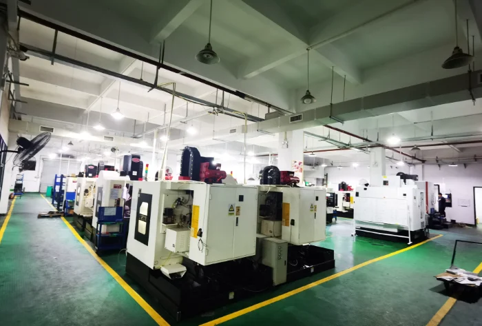
In modern CNC manufacturing systems, end milling is involved in almost all critical shaping operations of structural and functional parts. Whether it is aluminum components, steel mechanical parts, or complex mold cavities and 3D surfaces, end milling plays an irreplaceable role. However, in real production, many people use end milling every day without fully understanding its cutting principles, process limits, parameter logic, and its true engineering position in manufacturing. This guide explains end milling systematically from an engineering perspective, helping you build a complete and practical understanding for real production decisions.

What Is End Milling?
Before discussing cutting strategies and parameters, it is necessary to clarify the basic definition and role of end milling in CNC machining systems.
Definition of End Milling
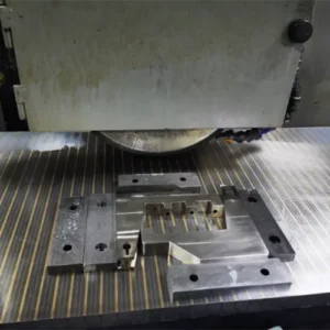
End milling is a CNC milling process that uses an end mill as the cutting tool. The tool can cut both axially and radially, allowing it to perform plunging, side milling, contouring, and profiling operations. Compared with single-direction cutting processes, end milling can cover the complete workflow from roughing to finishing.
Difference Between End Milling and Other Machining Methods
Compared with face milling (mainly for flat surfaces) or drilling (mainly for holes), end milling focuses more on:
- Complex geometry forming: Suitable for contours, pockets, steps, thin walls, and 3D surfaces.
- Multi-direction cutting capability: More features can be completed in one setup, reducing positioning errors.
- Wide process coverage: The same tool family can be used from roughing to finishing.
Why End Milling Is a Core CNC Process
In real production, 70%–90% of the key features of structural parts are created by end milling, not by turning or drilling. It essentially defines the manufacturing capability limit of a machining workshop.
Working Principle and Cutting Modes of End Milling
To understand the engineering value of end milling, we must start from the cutting mechanism itself.
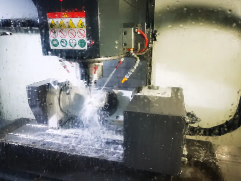
Multi-Edge Rotary Cutting Mechanism
An end mill removes material through high-speed rotation, with multiple cutting edges entering the cutting zone in sequence. Compared with single-edge cutting, this provides more stable load distribution and better surface consistency.
Axial and Radial Cutting Combination
- Axial cutting: Used for plunging, ramping, pocket opening, and step-down cutting.
- Radial cutting: Used for side walls, contours, and profile finishing.
- Combined cutting: Used for complex contours and 3D surfaces, and is the basis of modern CAM toolpaths.
Influence on Machining Stability
Different cutting methods directly affect tool load direction, machine vibration, part deformation, surface quality, and tool life. For high-precision or low-rigidity parts, toolpath strategy is often more important than simply changing parameters.
Core Technical Characteristics of End Milling
From an engineering perspective, end milling has several key advantages:
- Multi-direction cutting capability:
One tool can plunge, side-cut, and contour, allowing more features to be finished in one setup and improving geometric accuracy. - High geometric freedom:
It can machine internal and external contours, pockets, steps, thin walls, and complex 3D surfaces. Essentially, CAM converts CAD geometry into flexible tool motion paths. - High-precision forming capability:
With tool compensation and step-by-step allowance control (roughing, semi-finishing, finishing), stable micron-level dimensional control can be achieved. - Scalable machining efficiency:
With adaptive clearing, constant load toolpaths, and helical entry, material removal rate can be increased without significantly increasing risk.
Main Application Types of End Milling
From an application point of view, end milling covers a wide range of machining scenarios:
- Surface milling:
Used for reference surfaces, mounting surfaces, and functional contact faces, focusing on flatness, parallelism, and consistency. - Slot milling:
Used for keyways, guide slots, and assembly slots. Deep or narrow slots are challenging due to chip evacuation and tool deflection. - Profile milling:
Determines the outer and inner boundaries of parts, focusing on wall straightness and corner quality. - Pocket milling:
Usually follows a process chain of roughing, semi-finishing, and finishing, with high requirements for toolpath strategy. - 3D surface milling:
Often uses ball nose end mills, controlling step-over and step-down to manage surface texture, widely used in molds and appearance parts. - Precision contour machining:
For thin-wall and slender structures, stability and deformation control are more important than pure speed.
Common End Mill Types and Applications
| Tool Type | Geometry | Main Purpose | Typical Application |
|---|---|---|---|
| Flat end mill | Flat end | Surface, slot, profile | General parts |
| Ball nose end mill | Spherical tip | 3D surfaces | Molds, curved parts |
| Corner radius end mill | With corner radius | Semi-finishing, heavy load | Cavities |
| Roughing end mill | Serrated edges | High-efficiency roughing | Stock removal |
| Long flute end mill | Long cutting edge | Deep cavities | Deep pockets |
| Stub end mill | Short, rigid | Precision walls | High-accuracy features |
| Coated end mill | With coating | Hard materials | Stainless steel, titanium |

Material Applicability of End Milling
Different materials behave very differently in terms of cutting force, heat conduction, and chip formation.
- Aluminum and non-ferrous metals:
Suitable for high speed and high feed, but prone to built-up edge. Sharp edges, good chip evacuation, and stable cooling are critical. - Carbon steel and alloy steel:
Very common industrial materials. Cutting force and heat are relatively high, so tool rigidity and wear resistance must be balanced carefully. - Stainless steel:
Tends to work-harden and generate heat. Proper coating, cooling, and stable cutting strategy are necessary to avoid rapid tool wear and poor surface finish. - Titanium and superalloys:
Poor thermal conductivity and high temperature in the cutting zone cause rapid tool wear. The goal is stability and predictability rather than extreme removal rate. - Engineering plastics and composites:
Main risks come from deformation, melting, or fiber tearing. Tool geometry, feed strategy, and fixturing must be optimized.
End Mill Tool Material and Coating Selection
In end milling operations, the choice of tool material and coating has a direct impact on cutting stability, tool life, and surface quality. Different workpiece materials behave very differently in terms of cutting force, heat generation, and chip formation, so using a universal tool for all materials is not realistic.
Quick Selection Principles
- Aluminum and non-ferrous metals:
Easy to cut but prone to built-up edge. Tool selection should focus on sharp edges, low adhesion surfaces, and smooth chip evacuation. - Carbon steel and alloy steel:
Cutting load and temperature are moderately high, so the tool must balance wear resistance, heat resistance, and edge strength. - Stainless steel and titanium alloys:
These materials tend to work-harden and concentrate heat. Machining strategy should prioritize process stability over maximum removal rate. - Hardened steel:
Usually machined with small depths of cut and requires very high wear resistance and thermal stability. - Plastics and composites:
Prone to deformation or melting. Tool selection should emphasize sharp edges and low heat generation.
Recommended Tool Material and Coating Reference Table
| Workpiece Material | Recommended Tool Material | Recommended Coating | Engineering Focus |
|---|---|---|---|
| Aluminum / Copper / Brass | Carbide | Uncoated / DLC | Prevent built-up edge, smooth chip flow |
| Carbon steel / Alloy steel | Carbide | TiAlN / AlTiN | Wear resistance, heat resistance |
| Stainless steel | Fine-grain carbide | AlTiN / TiSiN | Reduce work hardening |
| Titanium / Superalloys | High-performance carbide | AlTiN / TiSiN | Process stability first |
| Hardened steel (>45 HRC) | Ultra-fine grain carbide | TiAlN / AlTiN | High wear & thermal stability |
| Plastics / Composites | Carbide / PCD | Uncoated / DLC | Sharp edge, low heat |
Key Factors Affecting End Milling Quality
In real production, machining quality is determined by the combined effect of machine, tool, parameters, and cooling.
- Spindle speed:
Determines cutting speed and temperature. Too high causes excessive wear and heat; too low may cause unstable cutting. - Feed rate:
Controls chip thickness and cutting load. Improper feed often leads to vibration and surface defects. - Depth of cut:
Including axial and radial depth. This directly affects cutting force and rigidity requirements. - Tool material and coating:
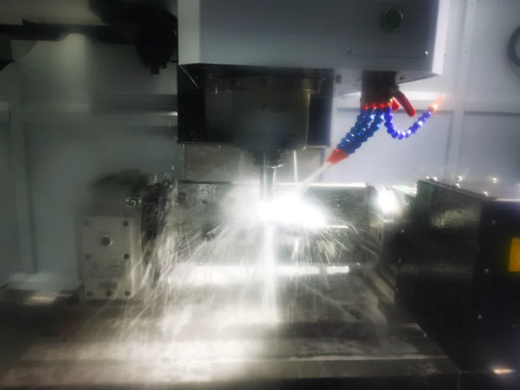
Affects wear resistance, edge strength, and thermal behavior. In difficult materials, tool choice often decides feasibility. - Cooling and chip evacuation:
Poor chip evacuation often causes secondary cutting and rapid tool failure, especially in deep cavities.
Conclusion: Engineering Position of End Milling
End milling is not just a simple milling operation, but a complete forming process covering roughing to finishing. It determines whether complex geometries can be manufactured reliably and directly affects dimensional accuracy, surface quality, and batch consistency. In modern CNC manufacturing, most critical contours and cavities depend on end milling, and its process maturity strongly reflects a company’s overall engineering and manufacturing capability.