Face Milling is one of the most fundamental and critical machining operations in CNC manufacturing. It is widely used to generate reference surfaces, assembly faces, and large flat areas on mechanical components. The stability and quality of a face milling operation not only determine the surface finish of the current process, but also directly influence the dimensional accuracy and process reliability of all subsequent operations. A systematic understanding of face milling principles, tooling systems, material-specific strategies, and process control methods is essential for any modern machining operation aiming for high efficiency and consistent quality.

What Is Face Milling?
Definition and Basic Concept of Face Milling
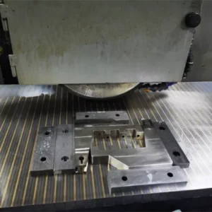
Face Milling is a milling process in which the cutter axis is perpendicular to the workpiece surface. Cutting edges located on both the face and the periphery of the cutter participate in material removal, producing a flat surface. Compared with using end mills for surface sweeping, face milling provides higher material removal rate, better surface consistency, and more stable flatness control, making it the preferred method for large-area planar machining and reference surface generation.
Basic Cutting Principle of Face Milling
During face milling, multiple inserts engage the workpiece simultaneously. Cutting forces are distributed between axial and radial directions, which improves cutting stability and productivity. Because several edges cut in each revolution, face milling is highly efficient, but it is also sensitive to cutter runout, insert height variation, and machine rigidity. A well-balanced cutter system and stable process conditions are essential for consistent results.
Main Types of Face Milling Operations
Conventional Face Milling: Used for general-purpose flat surface machining, focusing on stable cutting conditions, wide applicability, and reliable surface generation in most mechanical components.
High Feed Face Milling: Uses very small depth of cut and extremely high feed rate to achieve high productivity, especially suitable for roughing operations in molds and large cavities.
Heavy Duty Face Milling: Designed for large stock removal on castings and forgings, emphasizing tool strength, system rigidity, and stable load capacity.
Finishing Face Milling: Optimized for surface finish and flatness using sharper geometry and more precise cutter systems, often applied as the final planar machining step.
High Speed Face Milling: Common in aluminum and mold industries, combining high spindle speed and light cutting parameters to achieve both productivity and good surface quality.
Types of Face Milling Cutters
Indexable Face Mills: The most widely used type, offering flexible insert replacement, good economy, and wide material adaptability.
Solid Carbide Face Mills: Used mainly for small diameters, high-speed machining, or high-precision finishing, providing excellent rigidity and low runout.
PCD Face Mills: Mainly used for aluminum alloys, non-ferrous metals, and some plastics, offering extremely long tool life and superior surface finish.
CBN Face Mills: Used primarily for hardened steels and high-hardness materials in finishing operations, requiring high machine stability.
45°, 75°, and 90° Face Mills: Different entering angles affect cutting force direction, stability, and shoulder capability, and should be selected based on application and machine capability.
Advantages and Limitations of Face Milling
Advantages
Face milling provides high material removal rate, excellent surface consistency, good flatness control, and favorable cost per part in mass production. It is the most efficient method for generating large planar surfaces and functional reference faces.
Limitations
Face milling requires good machine rigidity, stable fixturing, and accurate cutter systems. It is not always suitable for very small, thin, or highly flexible parts, where deformation and vibration may become critical issues.

Tool Material Selection for Different Workpiece Materials (Encyclopedic Edition)
Material-tool matching is the core of stable face milling. Hardness, toughness, thermal conductivity, adhesion tendency, and elasticity of the workpiece material directly determine insert grade, coating, and geometry.
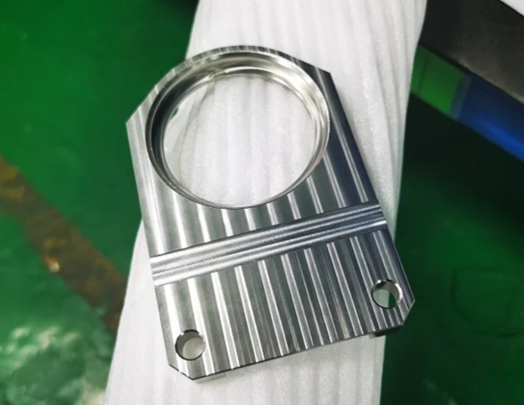
Aluminum Alloys: Aluminum is prone to built-up edge and chip adhesion. The cutter should use sharp, highly polished cutting edges with large positive rake angles. Uncoated carbide or DLC-coated inserts are preferred. For high-volume production or mirror-like surfaces, PCD face mills provide excellent surface finish and extremely long tool life.
Stainless Steel: Stainless steel work-hardens easily and has poor thermal conductivity. Inserts must emphasize toughness and heat resistance. TiAlN or AlTiN coated carbide inserts with stable edge preparation are commonly used. Overly sharp geometry should be avoided to reduce chipping.
Carbon Steel and Alloy Steel: These materials cover a wide hardness range. General-purpose coated carbide inserts are suitable for most applications. Softer steels favor wear resistance, while harder or interrupted cuts require tougher grades. Tool selection should balance productivity and tool life.
Titanium Alloys: Titanium generates high cutting temperatures and strong material rebound. Inserts should use high hot-hardness substrates and heat-resistant coatings with reinforced cutting edges. Cutting parameters should be conservative to control heat accumulation and avoid plastic deformation of the cutting edge.
Brass: Brass machines easily but can produce burrs and surface smearing. Sharp, high-positive geometry inserts are recommended, usually without heavy coatings. The focus should be on edge quality and cutter runout control.
Bronze: Some bronze alloys are abrasive. Compared to brass, more wear-resistant carbide grades are needed, while still maintaining reasonably sharp edges to avoid surface tearing.
Plastics (ABS, POM, PEEK, PMMA, PA, PC, PET, PTFE): Plastics are sensitive to heat, smearing, and deformation. The core principles are extremely sharp edges, polished rake faces, low friction, and efficient chip evacuation.
ABS focuses on reducing friction heat; POM requires good chip control; PEEK needs low heat input and stable cutting; PMMA demands mirror-polished ultra-sharp tools; PA needs low cutting force geometry; PC requires low-friction polished tools; PET needs clean chip evacuation; PTFE requires ultra-sharp tools and strong workpiece support.
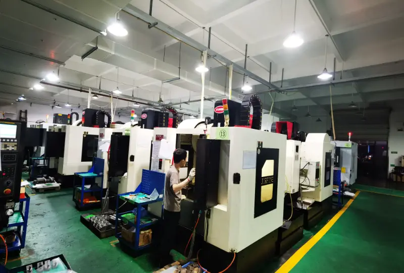
Face Milling on 3-Axis, 4-Axis, 5-Axis CNC and Manual Machines
3-Axis CNC: The most common and cost-effective solution for standard flat surfaces, with good stability and simple programming, but limited for multi-angle parts.
4-Axis CNC: Allows multiple faces or angled planes to be machined in one setup, reducing re-clamping and improving geometric consistency.
5-Axis CNC: Optimizes tool orientation for best cutting conditions, improving surface quality and tool life in complex parts, but with higher investment and programming complexity.
Manual Milling: Suitable mainly for repair work, prototypes, or very small batch production, with limited efficiency and repeatability.
Efficiency and Cost Consideration: Higher-axis machines offer more flexibility and fewer setups, but also involve higher equipment and programming costs. The choice should be based on part complexity and total manufacturing cost.
Typical Components and Structures Using Face Milling
Machine Structural Reference Surfaces: These surfaces serve as the primary datum for subsequent machining operations, and their flatness and consistency directly determine the dimensional stability of the entire part.
Mold Parting Surfaces: In mold manufacturing, the parting surface controls alignment accuracy and sealing quality, and face milling establishes the main reference plane before finishing and polishing.
Equipment Mounting Bases: These surfaces require good flatness and contact area to ensure uniform load distribution and long-term operational stability.
Fixture and Jig Base Plates: Fixture base surfaces determine the repeatability and positioning accuracy of the entire fixturing system.
Box-Type Components: Housings and gearboxes usually contain multiple interrelated planes, and face milling establishes unified reference surfaces controlling parallelism and perpendicularity.
Large Plate Components: Large plates are prone to deformation due to residual stress and clamping forces, and face milling also plays a role in geometry stabilization.
Process Parameters and Machining Strategy in Face Milling
Cutting Speed, Feed Rate, and Depth of Cut: These three parameters must be matched properly to maintain true cutting instead of rubbing, otherwise excessive heat and unstable tool life will occur.
Climb Milling vs Conventional Milling: On CNC machines, climb milling is generally preferred because it reduces cutting forces, improves surface quality, and extends tool life.
Entry and Exit Strategy: Smooth ramped or arc entry and exit reduce impact loads and prevent insert chipping.
Cutter Runout and Insert Height Consistency: Even small deviations will cause uneven load distribution, poor surface finish, and accelerated tool wear.
Workholding and Fixturing Stability: Poor clamping can easily cause deformation and flatness errors, especially on large or thin parts.
Chip Evacuation and Surface Protection: Poor chip control can cause surface scratching and secondary cutting, making coolant or air management important.

Common Face Milling Problems and Engineering Solutions
Surface Waviness and Vibration: Usually caused by insufficient rigidity, excessive tool overhang, or unstable cutting load.
Insert Chipping or Premature Failure: Often related to incorrect insert grade, excessive thermal load, or improper entry strategy.
Flatness and Parallelism Errors: Commonly caused by part deformation, unstable fixturing, or poor reference planning.
Surface Scratches and Smearing: Typically caused by poor chip evacuation or damaged cutting edges.
Other Milling Processes Related to Face Milling
End Milling: Primarily used for side walls, pockets, and profiles rather than large flat surfaces, focusing on contour generation and three-dimensional shape machining.
Side Milling: Used for machining vertical faces and steps, emphasizing side-edge cutting capability and often combined with face milling to complete multi-surface parts.
Slot Milling: Dedicated to machining keyways, grooves, and slots, requiring good tool rigidity and efficient chip evacuation.
Profile Milling: Mainly used for complex outer contours where toolpath accuracy is more important than material removal rate.
Pocket Milling: Used for internal cavity machining and usually combines roughing and finishing strategies.
High Speed Milling: Emphasizes small depth of cut, high spindle speed, and high feed rate, often used together with face milling in aluminum and mold machining.
Trochoidal Milling: Uses special toolpaths to reduce cutting load and heat concentration in difficult materials, typically applied in roughing stages.
Conclusion: Building a High-Efficiency and High-Stability Face Milling System
A robust face milling system is the result of systematic integration of tool systems, material characteristics, machine tool capability, process strategy, and standardized operation methods. Only by treating face milling as an engineering system rather than a simple operation can manufacturers achieve predictable quality, stable productivity, and long-term cost control.if you want know more details,please feel free to contact with us.