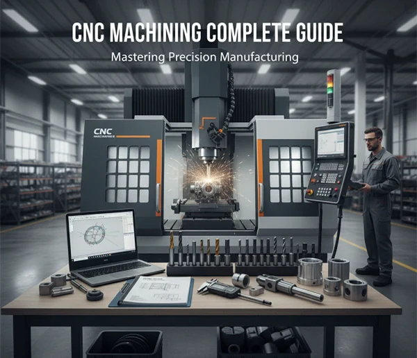
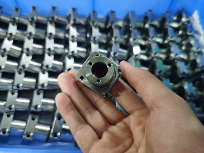
CNC (Computer Numerical Control) machining is a high-precision manufacturing process that uses computer programs to control machine tools for automatically cutting metal or plastic parts. Its core advantages lie in high precision, high efficiency, and strong repeatability.
Below is a detailed introduction to the standard execution steps of CNC Machining Complete Guide:
Product Design and 3D Modeling (Design & CAD Modeling)
Design three-dimensional part models using professional CAD software (e.g., SolidWorks, AutoCAD, or CATIA);
Define critical dimensions, tolerances, thread specifications, chamfers, and fit requirements;
Export files in standard formats such as .STEP, .IGES, or .DXF;
Incorporate machining allowances during design to ensure process stability.
Objective: Generate engineering-compliant 3D models providing accurate data for programming and process planning.
Process Planning & CAM Programming
Import CAD models into CAM software (e.g., Mastercam, Fusion 360, UG NX);
Select machine tool type (e.g., 3-axis, 4-axis, or 5-axis CNC machine);
Set cutting tools, rotational speed (RPM), feed rate, and cutting depth;
Simulate tool paths to prevent interference or collisions;
Output G-code and M-code—machine-recognizable control instructions.
Objective: Convert design drawings into executable machining programs for precise and efficient processing.
Machine Setup & Workpiece Mounting
Select appropriate tools (milling cutters, drills, taps, etc.) and fixtures (vices, magnetic chucks, jigs, etc.);
Securely mount the workpiece on the worktable to maintain stable positioning;
Calibrate tool length, tool setting points, and establish the workpiece coordinate origin;
Inspect machine status: coolant, lubricant, air pressure, power supply, and safety devices.
Objective: Ensure equipment is in optimal condition to prevent dimensional deviations caused by clamping errors or equipment malfunctions.
Dry Run & Simulation
Perform a dry run to verify toolpaths;
Simulate the machining process using CAM simulation or the machine control system;
Check for program errors, tool collisions, or path boundary violations;
Conduct test cuts on critical machining areas to validate dimensions and surface quality.
Objective: Prevent tool collisions and material waste, ensuring program safety and reliability.
Rough Machining
Rapidly remove excess material from the blank using larger feed rates and cutting depths;
Employ wear-resistant tools (e.g., carbide tools) to enhance efficiency;
Retain a small allowance for subsequent semi-finishing operations;
Monitor tool wear and workpiece temperature changes during machining.
Objective: Quickly establish the part’s general contour, providing a stable foundation for subsequent finishing operations.
Semi-Finishing & Finishing
Adjust cutting parameters and use high-precision tools for dimensional correction;
Focus on machining critical surfaces, mating holes, and high-precision areas;
Perform burr removal and chamfer grinding on part edges near the end of machining;
Control dimensional tolerances within design specifications;
Finishing typically utilizes lower feed rates and smaller cutting depths;
Ensure surface roughness meets design requirements (e.g., Ra ≤ 0.8μm).
Post-CNC machined parts must undergo deburring per ISO 13715 standards:
Functional surface burr height ≤ 0.05mm
Fitting surfaces require C0.3-C0.5mm chamfers
Automated grinding employs 6-axis robots + nylon grinding heads (3000rpm)
Objective: Achieve high dimensional accuracy and smooth surface finish.
Differences between 3-Axis, 4-Axis, and 5-Axis cnc Machining and Recommended Selection
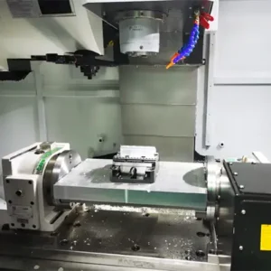
3-Axis cnc Machining: Basic and Efficient, Suitable for Simple Structures
3-Axis Machining: Basic and Efficient, Suitable for Simple Structures
Principle: The tool moves along the X, Y, and Z linear axes, while the workpiece remains stationary.
Applicable Parts:
Plane, grooves, holes, 2D contours (such as instrument panels and brackets)
Simple 3D surfaces (requiring multiple clamping)
Advantages:
Low Cost: The equipment has a simple structure, resulting in low maintenance and operating costs.
High Efficiency: Simple machining paths and fast programming make it suitable for small to medium-volume production (e.g., 50-5,000 parts).
Stable Precision: The issue of zero centerline speed of the ball cutter can be alleviated through process optimization, making it suitable for molds with low precision requirements.
Limitations:
Unable to machine complex surfaces; side machining requires multiple clampings, which can easily introduce errors.
Efficiency decreases significantly when machining deep cavities or special-shaped holes.
Recommended Applications:
Businesses with limited budgets who need to quickly produce simple parts.
Machining non-core components in the aerospace and automotive industries (e.g., aluminum alloy brackets).
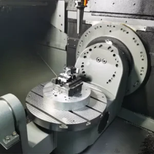
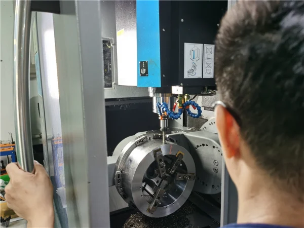
4-axis cnc machining: Flexible and efficient, suitable for polyhedral parts.
Principle: Adding a rotary axis (A or B) to a three-axis machining system allows the workpiece to rotate, allowing the tool to machine from multiple angles.
Applicable parts:
Cylindrical parts, parts with side holes (such as turbines, worm gears, and propellers);
Box-shaped parts, polyhedral parts (where multiple vertical surfaces need to be machined continuously);
Advantages:
Reduced clamping times: Multiple surfaces can be machined in a single clamping, improving efficiency by 30%-50%.
Improved precision: Precise positioning of the rotary axis avoids secondary clamping errors, making it suitable for inclined surfaces or features with specific angles.
Cost controllable: The equipment cost is similar to that of a three-axis machining system, but the machining capacity is significantly enhanced.
Limitations:
Under intensive use, the worm gear mechanism can experience high wear.
Complex parts require frequent adjustment of the rotary axis angle, increasing programming complexity.
Recommended applications:
Businesses with limited budgets needing to machine complex curved surfaces (such as molds and pharmaceuticals).
Non-core precision parts in the aerospace industry (such as shoe molds and mannequins).
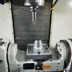
5-axis cnc machining: Versatile and precise, suitable for high-end manufacturing.
Principle: Adding two rotary axes (two of the A/B/C axes) to a 3-axis machining center allows the tool to approach the workpiece at any angle.
Applicable parts:
Complex curved surfaces (such as aircraft blades and turbine blades);
Specially shaped structural parts (such as orthopedic implants and optical lenses);
Mold cavity parts (requiring single-stage molding).
Advantages:
Multi-surface machining in a single clamping setup: Avoids interference, overcutting, and undercutting, increasing efficiency by over 50%.
Ultra-high precision: Reaching submicron levels (±0.001mm), suitable for high-end applications such as optics and medical.
Wide material compatibility: Capable of machining hard materials such as titanium alloys and ceramics.
Limitations:
High equipment cost: 2-3 times that of a three-axis machining center, and complex maintenance and operation.
High programming difficulty: Requires multi-axis toolpath planning, collision detection, and tool axis vector control.
Recommended applications:
Machining of core components in high-end manufacturing industries such as aerospace, energy, and power generation.
Parts requiring extremely high precision (such as artificial joints) in the medical and precision instrument industries.
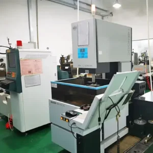
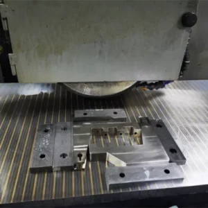
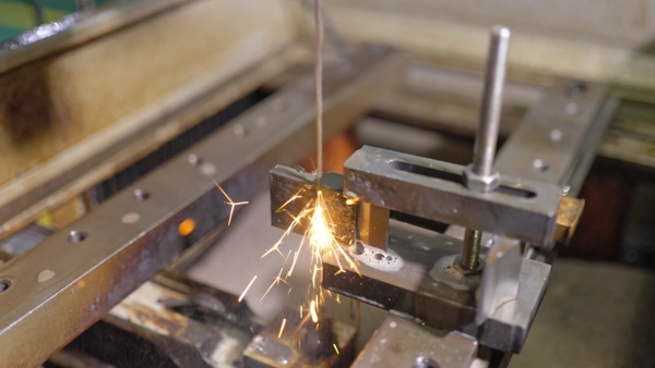
Wire EDM machining (EDM)
In CNC machining, EDM is a critical process for handling high-hardness materials (HRC 50+) and complex cavities. It also removes excess material from milled parts to prevent deformation:
Fast Wire EDM
Description: A high-speed wire EDM (WEDM-HS) uses a molybdenum wire as the electrode, reciprocating at a speed of 8-10 m/s. It removes metal through spark discharge, achieving a single cut.
Accuracy: ±0.01mm, surface roughness Ra 1.25-2.5μm, meeting general machining needs.
Processing Speed: Cutting speeds have generally increased from 20-40 mm²/min to over 100 mm²/min, with a maximum of 260 mm²/min.
Processing Cost: Low cost, simple structure, and affordable, making it suitable for high-volume, low-precision machining.
Medium Wire EDM
Description: Medium-wire EDM (MS-WEDM) machines fall into the high-speed wire cutting category, enabling multiple cuts. Roughing with molybdenum wire runs at high speeds (8-12 m/s), while finishing with lower speeds (1-3 m/s).
Precision: ±0.003 mm, surface roughness Ra 0.65 μm, resulting in higher machining quality than fast wire cutting.
Processing Speed: Approximate to fast wire cutting, with speed reduced for improved quality during multiple cuts.
Processing Cost: A moderate balance between cost and efficiency, retaining the advantages of fast wire cutting while improving quality through multiple cuts. Suitable for medium-precision machining.
Slow Wire EDM
Description: A low-speed wire EDM (WEDM-LS) uses a slow, unidirectional wire electrode, moving at speeds below 0.2 m/s, and is discontinued after discharge.
Accuracy: ±0.001mm, surface roughness Ra minimum 0.05μm, achieving high machining quality. Processing Speed: Maximum 400 mm/min, slower than fast wire cutting, resulting in high-quality machining of complex parts.
Processing Cost: High cost and expensive equipment, with disposable electrode wire. Suitable for high-precision, complex mold machining.
The Differences Between fast Wire EDM, Slow Wire EDM, and Medium Wire EDM:
Fast Wire EDM
Offers the fastest processing speed and is suitable for simple shapes, thin-walled parts, flat surfaces, and high surface roughness.
Applications: Rapid metal cutting and the production of low- to medium-precision molds or parts. Suitable for small- to medium-sized production runs with tight deadlines.
Medium Wire EDM
Offers speed and accuracy between high- and slow-speed wire EDM, balancing processing time and surface quality.
Applications: Mold processing and medium-precision cutting of mechanical parts. Suitable for mass production or where a balance between precision and efficiency is required.
Slow Wire EDM
Offers slower processing speeds but high precision and surface quality, with minimal thermal deformation, making it suitable for complex and precision machining.
Applications: Processing high-precision, high-surface-quality parts, such as those in aerospace, medical devices, and high-end mold manufacturing.
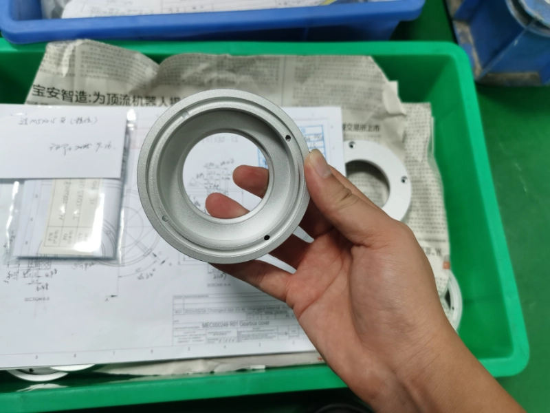
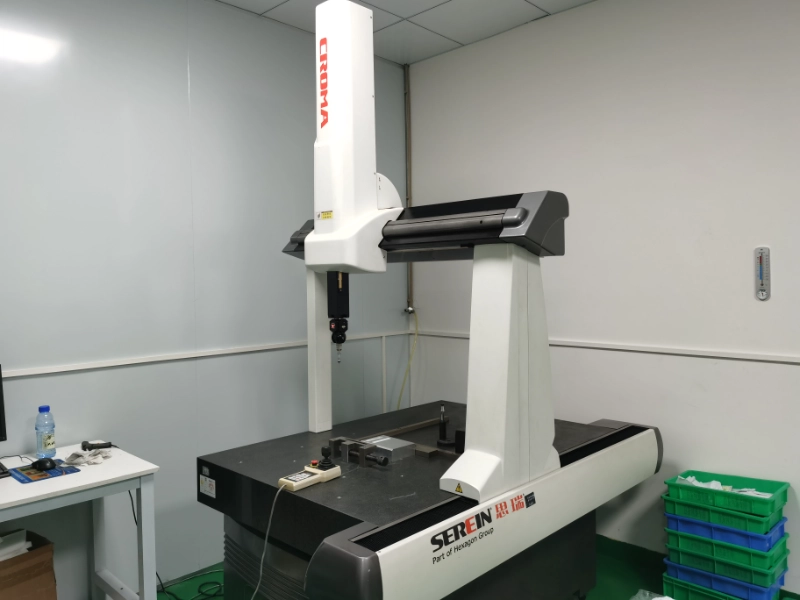
Inspection & Quality Control
Post-machining measurements are performed using specialized tools:
Vernier calipers, micrometers, depth gauges (for rapid inspection)
Coordinate Measuring Machine (CMM) (high-precision dimensional inspection)
Surface Roughness Tester (Ra value measurement)
Geometric accuracy checks (perpendicularity, concentricity, flatness, etc.)
Inspection results are documented and archived; process parameters are adjusted promptly if deviations occur.
Objective: Ensure each part meets tolerance requirements and customer standards (e.g., ISO 2768).
Post-processing & Finishing
Manually remove burrs from areas inaccessible to grinding tools and clean workpieces;
Perform necessary surface treatments:
Polishing, sandblasting, anodizing, electroplating, passivation, etc.;
Mark part numbers or laser engrave;
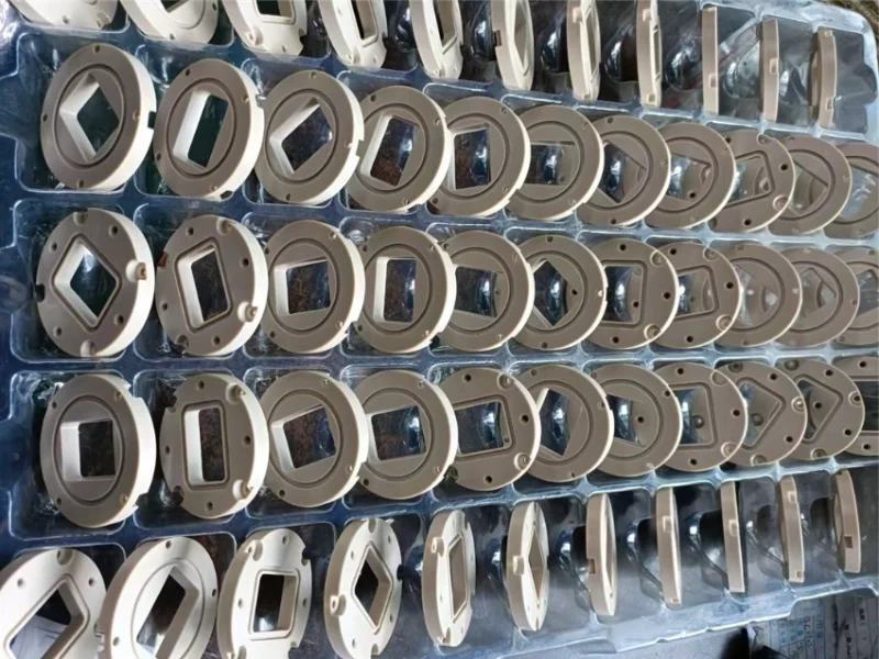
Protectively package to prevent shipping damage.
Objective: Enhance product appearance, corrosion resistance, and functional performance.
Data Feedback & Process Optimization
Store machining parameters, tool life, and inspection data;
Summarize experience to optimize tool paths, fixture designs, or cutting parameters;
Establish a standardized CNC machining database;
Provide repeatable, traceable process solutions for similar parts.
Objective: Achieve continuous improvement, enhance production consistency and efficiency.
Summary of CNC Machining Complete Guide
CNC machining is a highly automated precision manufacturing technology where every step—from design modeling to inspection optimization—directly impacts part quality and production efficiency.
Through standardized processes, scientific programming, and rigorous inspection, it achieves high precision, stability, and consistency in production outcomes. If you have CNC-machined components to produce, contact Weldo Machining for the latest quote.