CNC machining tolerance, the controlled deviation range between actual and design dimensions (typically ±0.001 inches to ±0.005 millimeters), is crucial in connecting design specifications with actual functionality, determining product performance and safety. It executes G-code instructions generated from 3D CAD models using computer-controlled tools, enabling the machining of various materials such as aluminum alloys, titanium alloys, and plastics.
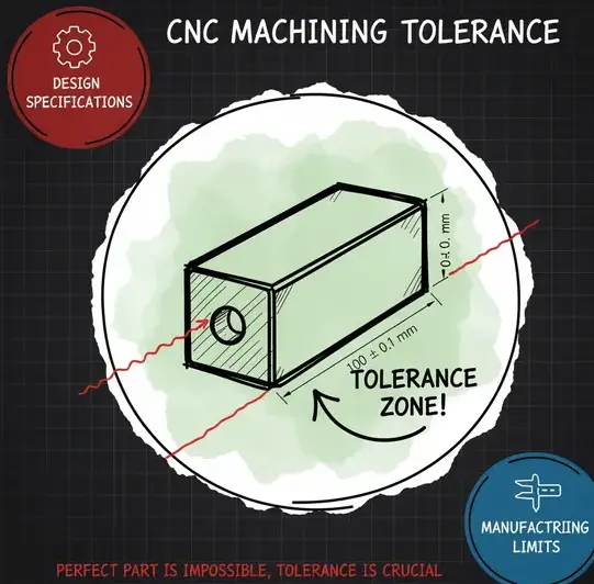
Definition and Significance of CNC Machining Tolerance
CNC machining tolerance refers to the permissible deviation between the actual and specified dimensions during machining, directly affecting product function and quality. Its core categories are three: dimensional tolerance (e.g., ±0.01mm linear dimensions), geometrical tolerance (including shape errors such as flatness ≤0.005mm/100mm, positional errors such as perpendicularity ≤0.002mm/100mm), and surface roughness (Ra value).
Key Tolerance Types
Dimensional Tolerance: Controls dimensional variations (e.g., ±0.005mm for precision parts).
Geometric tolerances: Controlling geometric accuracy (e.g., roundness ≤ 0.003 mm, parallelism ≤ 0.01 mm/100 mm).
In industry, stringent CNC machining tolerances ensure part interchangeability and performance. For example, excessively large tolerances in automotive transmission gears can lead to abnormal noise and shortened lifespan, while medical implants require micron-level precision to avoid tissue irritation. Conversely, overly stringent tolerances increase costs—achieving ±0.001 mm can increase production costs by 30% due to specialized equipment and extended machining time. Therefore, balancing tolerance requirements with manufacturing feasibility is crucial for industrial efficiency and product reliability.
Industry-Specific CNC Machining Tolerance Standards
CNC machining tolerance standards vary by industry and are driven by functional requirements and safety regulations. Internationally, ISO 286 and ANSI/ASME B4.2 are the basic frameworks: ISO 286 defines tolerance grades such as IT5 (±0.013 mm for a 300 mm dimension), while ANSI/ASME B4.2 adapts ISO’s limits and fit systems for US engineering, emphasizing thermal stability and dynamic performance verification. Aerospace: Micrometer-Level Precision in Extreme Environments
Aerospace components require tolerances of ±0.002 mm for critical structures such as turbine blades and landing gear. For example, Boeing 787 engine parts use slow wire EDM to machine TC4 titanium alloy, achieving 0.1 μm precision and ensuring fatigue resistance 1819 at an operating temperature of 1600°C. Inspection relies on laser interferometers and coordinate measuring machines (CMMs) with ±0.5 μm precision to verify geometric tolerances such as concentricity and flatness.
Medical: Regulatory-Driven Microprecision
Medical devices, particularly orthopedic implants, require tolerances of ±0.005 mm to ensure biocompatibility and anatomical fit. 100% inspection is required to meet FDA 21 CFR Part 8 requirements, such as cobalt-chromium alloy joint prostheses using 0.03 mm electrode wires and temperature-controlled machining. Surface roughness (Ra ≤ 0.4 μm) is crucial for preventing bacterial adhesion and is verified using white light interferometers.
Automotive: Balancing Precision and Cost Efficiency Automotive tolerances prioritize mass production feasibility. According to SAE J400 standards, transmission gears are typically maintained at ±0.02mm. Wire EDM achieves ±0.005mm precision in injection molds, while door panel stamping dies maintain ±0.05mm contour precision to reduce wind noise. Statistical process control (CPK≥1.33) ensures consistency across production runs of 100,000+ units.
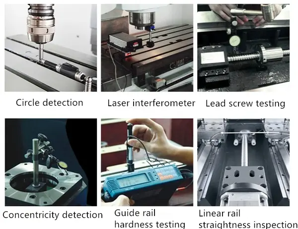
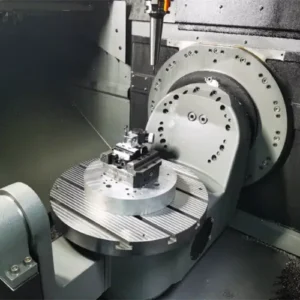
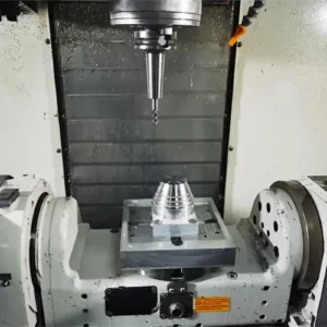
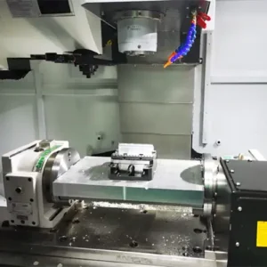
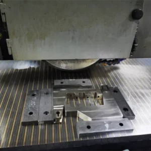
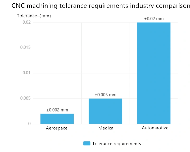
Caption: CNC machining tolerances are verified through six key inspection procedures, including circular arc trajectory testing, laser interferometry, lead screw inspection, motor mount concentricity measurement, guide rail hardness testing, and linear guide rail straightness evaluation. Key Tolerance Comparison: Aerospace: ±0.002mm (engine blades), IT5 grade; Medical: ±0.005mm (implants), conforming to ISO 13485; Automotive: ±0.02mm (gears), SAE J400 standard.
Relationship between Precision Grade, Manufacturing Cost, and Material Waste
Precision requirements in CNC machining directly impact manufacturing costs and material waste, forming a key three-way relationship in production economics. When the precision grade tightens from ±0.1mm to ±0.001mm, both machining costs and material waste rates show a significant upward trend.
Precision-Cost-Waste Correlation Matrix
The table below illustrates the quantitative relationship between precision tolerance, cost coefficient, and material waste rate, based on industry benchmarks and machining practices:

| Precision tolerance | Cost coefficient | Material waste rate |
| ±0.1 mm | 1.0 | 3% |
| ±0.05 mm | 1.5 | 5% |
| ±0.01 mm | 2.2 | 8% |
| ±0.005 mm | 2.8 | 10% |
| ±0.001 mm | 3.5 | 12% |
Note: The cost factor is based on ±0.1mm (1.0); the waste rate reflects the subtractive processing loss of metal materials.
Economic Impact of Precision Upgrades
Stricter CNC tolerances require advanced CNC equipment (e.g., $75-150 per hour for a 5-axis machine versus $40 per hour for a 3-axis machine), specialized tools, and extended machining times. For example, achieving ±0.001mm accuracy requires 5-8 times longer machining cycles than ±0.05mm tolerance, and for hard metals like Inconel 718, tool wear increases by 40%. This further amplifies costs—for titanium alloys costing $30-100/kg, a 12% loss rate results in an additional $120-400 wasted per cubic meter.
Case Study: The Risks of Overly Precision
A US aerospace component manufacturer incurred a 40% cost overrun when specifying a ±0.0005mm tolerance for turbine blade fixtures. Metrological verification showed that functionality required only ±0.005mm accuracy. Excessive Tolerance Requirements:
Material-Specific Waste Dynamics
Difficult-to-machine materials exacerbate waste:
Titanium alloys: A 12% waste rate is equivalent to $240/kg for medical implants.
Stainless steel: Laser cutting reduces waste from 15% to 5% compared to conventional milling.
Composite materials: GFRP processing generates 20% waste due to delamination.
Optimization strategies include nested layout (increasing sheet utilization to 92%) and hybrid manufacturing, reducing waste in complex geometries by 50%.
In short, precision optimization must be aligned with functional requirements to avoid the “tolerance trap“—excessive precision increases costs without performance gains. Manufacturers should conduct tolerance sensitivity analyses, prioritizing critical dimensions while relaxing non-essential dimensions to achieve economic sustainability.
The Impact of Surface finish on CNC Machining Tolerances and Solutions
Surface finish such as anodizing and electroplating significantly affect CNC machining tolerances through material deposition or chemical reactions. Anodizing generates an Al₂O₃ film through electrolysis, and the dimensional changes vary depending on the process: ordinary anodizing increases the single-sided dimension by 1/3 of the film thickness, while hard anodizing results in a 1/2 increase. For example, a 15μm hard anodized film results in a 7.5μm single-sided increase. Electroplating deposits metal ions (such as chromium and nickel) on the surface, with typical coating thicknesses of 5-50μm, directly increasing the workpiece dimensions.
To mitigate these effects, pre-processing compensation adjusts the design dimensions by subtracting the expected coating thickness. For example, if anodizing is expected to increase the dimension on one side by 0.0003 inches, the processing dimension is reduced by that value. A laser thickness measurement feedback system monitors the coating thickness in real time to ensure it remains within tolerances.
Key Control Strategies
Pre-compensation: Design dimension = Finished size – Expected coating thickness (e.g., 0.0003 inches for anodizing).
Masking: Protect untreated areas to limit dimensional variations.
Real-time monitoring: The laser system tracks coating thickness during processing.
These methods, combined with stringent process parameter control (e.g., anodizing temperature 0-10°C, plating current density 1-5 A/dm²), ensure that CNC parts meet stringent machining tolerances even after surface treatment.
Case Study: CNC Machining Tolerances in the International Industry
Aerospace Sector
In a project machining aero-engine turbine blades (SUS304 stainless steel), dimensional stability requirements under high temperature and high speed conditions were met, and the CNC machining tolerances for key holes needed to be controlled within ±0.01 mm. The component faced the dual challenges of material cutting hardening (hardness HRC 45+) and machining deformation due to its thin-walled structure (1.8 mm). The solution employed a 5 axis CNC machining center with coated carbide tools, using a “roughing (feed rate 3000 mm/min) + 2 finishing” process, and integrating an online laser measurement system for real-time deformation compensation. The final blade geometric accuracy error was ≤±2 μm, and the dynamic balance was <0.09 g·mm, meeting the stringent requirements of ASME Y14.5 standards for aerospace components.
Medical Industry
Cobalt-chromium alloy artificial joint molds utilize 0.03 mm galvanized electrode wire in a constant-temperature (20±0.5℃) machining environment to achieve a CNC machining tolerance of 0.005 mm for complex curved contours. Through a self-developed “micro-stress machining process,” the thickness of the heat-affected zone is reduced from 50 μm to below 10 μm, improving the fatigue life of the implant by 30%. This process meets FDA biocompatibility requirements for implantable devices, increasing the bone integration area of the porous structure of the hip joint stem by 40% compared to traditional processes, with a surface roughness of Ra 0.05 μm.
Automotive Manufacturing
A new energy vehicle battery casing (6061-T6 aluminum alloy) machining project requires stable dimensional tolerances of ±0.05 mm (f-level accuracy) and flatness of 0.02 mm/m during mass production. The process employs a “rough milling + high-speed finish (10,000 rpm spindle)” technique using a Japanese Fanuc Robodrill machining center, achieving one-time T-slot forming through U-axis oscillation. Statistical Process Control (SPC) shows a critical dimension CPK value of 1.67, with a defect rate controlled below 0.3%. This solution reduces the assembly gap between the battery casing and the module from 0.2 mm in traditional processes to 0.08 mm, improving heat dissipation efficiency by 15%.
Cross-Industry Tolerance Control Comparison
| Industries | Typical tolerance requirements | Key Challenges | Key technological methods |
| Aerospace | ±0.005~±0.01 mm | High-Temperature Material Deformation | 5 axis machining + online measurement |
| Medical | ±0.005 mm | Balancing Biocompatibility and Precision | Micro-stress machining + constant temperature control |
| Automotive | ±0.03~±0.05 mm | Mass Production Consistency | High-speed precision finishing + SPC process control |
Optimization Strategies for CNC Machining Tolerance Control
Optimizing cnc machining tolerances requires integrating design, machining, and inspection methods. In the design phase, Design for Manufacturability (DFM) reviews simplify tolerance requirements by identifying non-critical features and adjusting geometry, such as increasing the wall thickness of thin-walled structures to ≥1.5mm to avoid deformation. The machining phase employs adaptive control systems, such as spindle load feedback to adjust feed rates, and multi-stage cutting strategies (roughing → semi-finishing → finishing) with parameter optimization (e.g., 1500-3000 rpm spindle speed, 0.1-0.3 mm/r feed rate for 6061 aluminum alloy). Inspection relies on laser interferometers (accuracy ±0.5μm) for real-time monitoring and periodic calibration (every six months).
Case Study: Weldo machining centers utilize digital twin technology to simulate processes, reducing CNC machining tolerance fluctuations by 30% through predictive error compensation. This integrated strategy ensures tolerance control in complex scenarios, from aerospace components (±0.005mm) to consumer electronics (±0.1mm).
Key Measure Summary
Design: DFM review simplifies tolerances and avoids unnecessary complexity.
Machining: Adaptive parameter adjustment and multi-stage cutting with precision tools.
Inspection: Laser interferometry is used for real-time monitoring and periodic calibration.
Conclusion: Future Trends in CNC Machining Tolerances
CNC machining tolerances, balancing quality and cost, are advancing towards intelligent and nanometer-level precision. Quantum sensing may boost accuracy to sub-nanometer by 2030, while AI-driven programming cuts design time. Digital twins and IoT enable remote monitoring, with 55% of new tools being intelligent, driving “digital factories.” Green and high-precision manufacturing co-evolve, like nano-coated tools extending life and saving energy. As a key competitiveness indicator, CNC tolerance evolution empowers aerospace and medical fields, reflecting precision manufacturing’s enduring pursuit.