部品に内側スプライン、キー溝、内歯車、角穴、またはその他の成形プロファイルが含まれている場合、, ミーリング, スロット加工, ワイヤー放電加工機, 、およびブローチ加工は、いずれも可能な選択肢のように思えるかもしれません。しかし、プロジェクトで寸法の一貫性、短いサイクルタイム、および反復生産が求められる場合、ブローチ加工の方がより現実的な選択肢となることがよくあります。.
ブローチ加工は、中・大量生産に特に適していますが、大量生産に限定されるわけではありません。 形状が複雑な部品、公差の厳しい内部形状、あるいは他の加工法ではコストがかさむ部品の場合、少量生産であってもブローチ加工が有効な場合があります。重要なのは、部品の形状、材質、熱処理状態、公差、および予想生産数量を総合的に評価することです。.
金属加工における「ブローチ加工」とは何か?
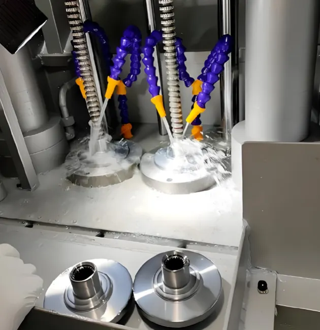
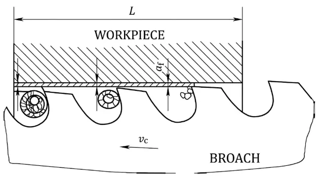
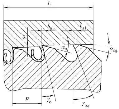
ブローチ加工とは、ブローチと呼ばれる多歯状の切削工具を、ワークピースの中や表面に沿って押し進めたり引き戻したりする加工方法です。各歯は前の歯よりもわずかに大きくなっているため、工具が直線的に移動するにつれて、切削余量が層ごとに除去されていきます。.
隣接する歯の高さまたは幅の差を「1歯あたりの上昇量」と呼びます。送り機構が工具自体に組み込まれているため、ブローチ盤では通常、主運動が1回だけで済みます。荒加工、半仕上げ、仕上げ、および寸法調整をすべて、1回の加工ストロークで完了させることができます。.
そのため、ブローチ加工は高速かつ高精度に行うことができます。ブローチ、ワークの固定方法、および加工パラメータが一度決定されれば、作業者の影響を最小限に抑えつつ、部品ごとに同じ形状を再現することができます。.
どのような機能について取り上げることができるでしょうか?
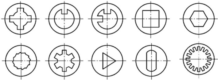
円形、正方形、長方形、六角形、多角形、および特殊形状の貫通穴
直壁型、インヴォルート型、鋸歯状、および特殊な内歯形
内側および外側のキー溝
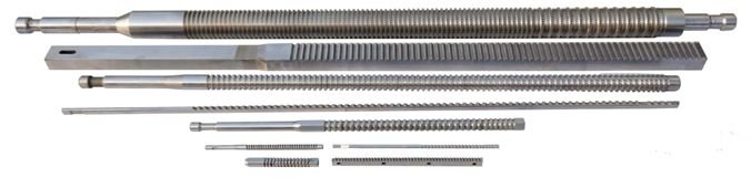
内歯車、外歯車、ラック、および部分歯形
平坦面、スロット、溝、ダブテール、および成形された外面
タービンおよびコンプレッサー部品用のモミの木型および鳩尾型
穴、スプライン、キー溝、面取り、またはサイズ調整の加工要素を1つの工具に統合した複合プロファイル
従来の直線ブローチ加工では、通常、切削される表面は工具の移動方向に対して平行な状態を保つ必要があります。また、内径ブローチ加工では、ブローチのパイロット部が挿入でき、かつ切りくずが切削路を通って排出されるのに十分な大きさの始孔が必要です。.
その部品はブローチ加工に適していますか?
ブローチ加工される部品は単純な形状である必要はありませんが、その形状は、工具が干渉することなく挿入、切削、切りくずの排出、および引き抜きを行えるものでなければなりません。以下の点は、実用的な初期チェックの指針となります。.
| デザインアイテム | 確認すべき事項 |
| 機能へのアクセス | 従来の内面ブローチ加工では、工具の出し入れを行うために貫通穴やその他の障害物のない経路が必要となります。. |
| プロファイルの方向 | 生成する面は、通常、ブローチ送り方向と平行である必要があります。. |
| 開始穴 | パイロットはスムーズに挿入できなければならず、穴は適切な大きさ、真円度、真直度、および位置を備えている必要がある。. |
| 部品の長さ | ブローチ加工の長さは、ブローチの切りくず排出スペースおよび強度限界の範囲内に収めなければなりません。. |
| 肉厚 | 薄かったり厚みが不均一な壁は、切削中に膨張し、ブローチが通過した後に元に戻ることがあります。. |
| 基準面 | 自動位置合わせ機能付きの支持具を使用する場合を除き、支持面は平らで、開始穴に対して直角である必要があります。. |
| 材質と硬度 | 加工性、熱処理状態、局所的な硬い箇所、および硬度のばらつきは、工具寿命や表面仕上げに影響を与えます。. |
| 寛容 | 寸法、形状、ピッチ、振れ、および表面仕上げの要件は、1つの一般的な公差に依存するのではなく、個別に定義すべきである。. |
| 生産量 | 専用ブローチは、繰り返し生産数量や年間需要が増えるにつれて、より経済的になります。. |
ブラインド穴、段付き穴、深部が遮蔽された形状、および切削方向に沿って形状が変化するプロファイルは、一般的に従来のブローチ加工には不向きです。ただし、深さや形状によっては、ロータリーブローチ加工やその他の加工方法が可能である場合もあります。.
不確実性がある場合は、工程が確定する前に、サプライヤーは2D図面と3Dモデルを確認すべきです。エントリ面取り、底面穴、肉厚、基準点設定、または公差にわずかな変更を加えるだけで、金型製作のリスクとコストを大幅に削減することができます。.
ブローチ加工はどのように行われるのか?
ブローチは、単に同一の切削歯が並んでいるだけのものではありません。その各セクションは、工具を誘導し、余肉を段階的に除去し、最終寸法を形成し、工具がワークから離れる際に工具を支える役割を果たします。.
シャンクとネック:ブローチを機械に取り付け、引張力または押圧力を伝達する。.
フロントパイロット:切削開始前に、あらかじめ用意された穴に挿入し、ブローチをワークピースに合わせます。.
荒削り、半仕上げ、仕上げ用の刃先:加工余量を段階的に除去し、所定の形状を形成します。.
歯および後部パイロットの寸法調整:最終的な寸法と仕上げを安定させ、ブローチを支持し、工具が引き抜かれる際に完成した表面を保護する。.
図面、材料、熱処理、公差、表面仕上げ、および生産数量を確認してください。.
ブローチ加工および治具に必要な、開始穴、基準面、および切り込み・切り出し面取りを準備する。.
ブローチを選定または製造し、機械のストローク、引張力、速度範囲、および工具の接続を確認する。.
スターター穴がブローチの移動方向と一致するように、ワークを位置決めし、固定します。.
指定された切削液を塗布した後、ブローチをワークピースに通すように、一回の制御されたストロークで引き抜くか押し込みます。.
歯の溝から切りくずを取り除き、ワークを清掃し、生産を再開する前に最初の部品を検査してください。.
生産工程全体を通じて、モニターのサイズ、表面状態、切削力、および工具の摩耗状況を監視する。.
ワークの保持と潤滑は極めて重要です。治具は、ワークを歪ませることなく切削荷重に耐えなければならず、一方、切削液は切削領域に到達し、摩擦を低減し、切りくずを排出する必要があります。内面ブローチ加工や水平ブローチ加工では、通常、開放型の外面加工や垂直加工に比べて、切削液の供給や切りくずの排出がより困難になります。.
ブローチ加工の主な種類にはどのようなものがありますか?
ブローチ加工は、加工対象となる表面、力の作用方向、工具の配置、およびワークの状態で分類することができます。それぞれの種類は、異なる生産上の課題を解決するものです。.
内径ブローチ加工
内面ブローチ加工は、あらかじめ加工された開口部の内部に形状を形成する加工法です。代表的な例としては、円形や多角形の穴、キー溝、内面スプライン、内歯車などが挙げられます。フロントパイロットおよび切削歯がワークを通過できるように、スターター穴が必要です。.
外径・面ブローチ加工
外径ブローチ加工は、開放面から材料を除去して、平坦面、スロット、溝、成形面、外歯、またはブレード根元形状を形成する加工法である。周囲の穴によって切削が自動中心合わせされるわけではないため、ワークと工具には堅固なガイドが必要となる。.
キー溝のブローチ加工
キー溝ブローチ加工では、ガイドブッシングまたはホーンを備えたキー溝ブローチを使用して、直線状の内部キー溝を形成します。キー溝の全深さを1回の加工で安全に切削できない場合は、数回に分けて加工を行い、その都度シムを追加することができます。これは、標準的な穴径やキーサイズにおいて、一般的かつ経済的な加工方法です。.
スプラインブローチ加工
スプラインブローチ加工は、1回のストロークで穴の周囲に複数の歯や溝を形成します。この加工法は、ギア、ハブ、カップリング、トランスミッション部品、ステアリング部品などに用いられる、直壁型、インヴォルート型、鋸歯状、および特殊なスプラインの加工に利用されます。また、図面上の要求に応じて、ブローチを用いて小径の寸法調整を行うことも可能です。.
プルブローチ加工
プルブローチ加工では、機械がブローチをワークピース内へと引き込みます。この加工では、工具には主に引張応力が加わるため、同等のプッシュブローチに比べて工具を長くし、より多くの歯数を設けることができます。この方式は、内径形状の加工や大量生産において広く採用されています。.
プッシュブローチ加工
プッシュブローチ加工では、工具が被加工材に押し込まれるため、工具には圧縮荷重がかかります。たわみや座屈を抑えるためには、ブローチを短くし、しっかりとガイドする必要があります。プッシュブローチ加工は、短いキー溝や小さな穴の加工、補修作業、および手作業や少量生産の現場でよく用いられます。.
ロータリーブローチ加工
ロータリーブローチ加工(ウォブルブローチ加工とも呼ばれる)では、ワークに対して回転する、わずかに角度のついた工具を使用します。 旋盤、マシニングセンター、またはスクリューマシン上で、小さな正方形、六角形、その他の多角形の形状を形成することができます。短い突起部や一部の盲穴の加工に適していますが、従来の直線ブローチ加工とは異なります。.
ポットブローチ加工
ポットブローチ加工では、内側を向いた歯を持つ環状の工具アセンブリを使用します。ワークピースをこの工具内に押し込んだり引き抜いたりすることで、外側のスプライン、歯車、または同様の円周形状を形成します。この加工法は、一般的にシャフトやその他の外歯付き部品の量産に適しています。.
ハードブローチ加工
ハードブローチ加工は、熱処理後に、あらかじめソフトブローチ加工された内側スプラインの仕上げを行うものです。 超硬ブローチは、硬度約45~65 HRCのワークピースから熱処理による歪みを取り除き、歯形、ピッチ精度、有効幅、振れ、および表面粗さを改善します。これには、高剛性の工作機械、厳密に管理された切削余量、正確な予備ブローチによる選別、および専用の工具が必要です。.
ブローチはどのような素材で作られているのですか?
ブローチの材質は、被削材の材質、硬度、切削速度、形状の複雑さ、予想される工具寿命、および工具の再研磨や再コーティングが必要かどうかといった要素に基づいて選定されます。.
| ブローチ材 | 代表的な使用例 | 主な考慮事項 |
| 従来の高速鋼 | 一般鋼、鋳鉄、および非鉄金属を中速で加工 | 靭性に優れ、製造や再研磨が容易であり、従来のブローチ加工に広く用いられている |
| コバルト系高速度鋼 | 合金鋼、ステンレス鋼、および発熱量の多い被加工物 | 従来のHSSよりも高い耐熱硬度と耐摩耗性を備えている |
| 粉末冶金法による高速度鋼 | 要求の厳しい仕様と、より長い生産ロット | きめ細やかで均一な組織を持ち、靭性、刃先強度、耐摩耗性のバランスが良好である |
| カーバイド | ハードブローチ加工、研磨材、および高速生産 | 耐摩耗性は高いが、衝撃靭性は低い。剛性の高い機械と安定した工程が必要である。 |
| 組立式またはモジュール式建築 | 大型、高価、または交換可能な切削部 | 鋼製本体にHSSまたは超硬切削刃を取り付けることができ、修理や交換を簡素化できます |
汎用ブローチにはM2が一般的に使用されますが、より高い耐熱硬度や耐摩耗性が求められる場合は、M35またはM42が選択されることがあります。具体的な鋼種は、単に材料名だけで決めるのではなく、切削試験の結果や被削材の状態に基づいて決定する必要があります。.
TiN、TiCNなどのコーティング、, AlCrN, 、あるいは用途に特化したコーティングを施すことで、摩擦や摩耗を低減することができます。ただし、コーティングでは、歯形の不備、切りくずスペースの不足、1歯あたりの上昇量の過大、位置ずれ、あるいは潤滑不足といった問題を補うことはできません。したがって、再研磨と再コーティングは、1つの管理された工具加工プロセスとして一元的に管理する必要があります。.
ブローチ加工にはどのような設備が必要ですか?
ブローチ加工システムには通常、工作機械、ブローチ、ワーク保持装置、工具の接続・ガイド機構、切削液システム、切りくず処理装置、安全ガード、および検査装置が含まれます。適切な工作機械の選定は、切削方向、ストローク、切削力、ワークのサイズ、および自動化の目標によって決まります。.
| 機器の種類 | 代表的な用途 | 主な特徴 |
| 横型ブローチ盤 | 長尺内面ブローチ加工および一般的なプルブローチ加工 | 工具へのアクセスや取り付けは簡単ですが、より広い設置スペースが必要で、切りくずの除去には細心の注意が必要です |
| 縦型ブローチ盤 | 内部生産、表面処理、および自動化生産 | 設置面積がコンパクト。ブローチに沿って作業台を引き下げたり、引き上げたり、持ち上げたりすることができます。 |
| 油圧ブローチ盤 | 汎用および高荷重の生産 | 滑らかで制御しやすい動きと大きな牽引力を発揮するが、作動油およびシステムのメンテナンスが必要である |
| サーボ駆動式ブローチ盤 | 精密生産および工程監視 | 速度と位置のプログラム設定が可能、安定した力制御、低消費電力、そしてデータ収集の容易化 |
| 平面ブローチ盤 | 平面、溝、鋳造面、および成形された外形 | 剛性の高いツールスライドと専用治具により、幅広い外径加工に対応 |
| 連続ブローチ盤 | 非常に大規模な表面生産 | ワークは、固定された工具または循環する工具の前を連続して通過する |
| ハードブローチ盤 | 熱処理を施した内部スプラインおよびその他の硬化形状 | 高い剛性、正確な位置合わせ、力のモニタリング、および超硬工具への対応 |
| CNCロータリーブローチ用アタッチメント | CNC旋盤またはマシニングセンターにおける短い多角形の穴 | 専用のリニアブローチ盤を必要としない、ロータリーブローチ加工向けのコンパクトなソリューション |
「水平型」と「垂直型」は機械のレイアウトを表し、「油圧式」と「サーボ式」は駆動システムを表します。これらは互いに競合する分類ではありません。例えば、垂直型の機械でも、油圧駆動とサーボ駆動のどちらを採用することも可能です。選択にあたっては、出力、ストローク、精度、サイクルタイム、メンテナンス、設置面積、および自動化の要件に基づいて判断する必要があります。.
手動ブローチ加工に適している部品はどれですか?
手動ブローチ加工は、主に短いキー溝、小さな角穴や多角穴、補修作業、試作品、および少量生産の部品に使用されます。標準的なプッシュブローチ、ガイドブッシング、シムセット、およびアーバープレスがあれば、専用の量産用ブローチ盤がなくても、こうした加工を完了できる場合が多くあります。.
セットアップは直角を保ち、剛性を維持しなければなりません。プッシュブローチは圧縮力によって動作するため、力の偏り、工具の長さが長すぎる、位置合わせ不良、あるいはプレスのたわみなどが原因で、工具が曲がったり破損したりする恐れがあります。適切に設計されたブローチを引っ張って使用することで座屈のリスクを低減できますが、その場合はブローチと接続部が引張荷重に耐えられるよう設計されている必要があります。.
手動ブローチ加工は、管理されていない現場での手抜き作業として扱ってはならない。特に、必要な切削力が高い場合や工具が特注品である場合は、プレス機の能力、工具のガイド、ガード、切削液、切りくずの排出、および作業者の安全について、すべて確認する必要がある。.
ブローチ加工は、どのような部品や産業で使用されているのでしょうか?
ブローチ加工は、成形された形状を正確かつ迅速に繰り返し加工する必要がある場合に用いられます。特に、その形状の加工に、ブローチ加工を用いないと複数の加工工程や繰り返しのインデックス操作が必要となる場合に、その価値が発揮されます。.
自動車用駆動系部品
代表的な用途としては、トランスミッションギア、ディファレンシャルベベルギア、ハブ、シンクロナイザースリーブ、パーキングギア、出力部品、ステアリングラック、カップリング、ドライブシャフトなどが挙げられます。内部スプラインやキー溝は、熱処理前に軟質ブローチ加工が行われることが多い一方、熱処理後の精度要件がより厳しい部品については、硬質ブローチ加工が施される場合があります。.
航空宇宙・エネルギー用部品
ブローチ加工は、タービンおよびコンプレッサーのブレード根元スロット、ファー・ツリー形状、ダブテール、ディスクスロット、その他の高精度な成形面などに用いられます。これらの部品には、高剛性の設備、厳密に管理された工具形状、安定した材料状態、そして徹底した検査とトレーサビリティが求められます。.
産業用機械部品
歯車、プーリー、スプロケット、カップリング、ブッシング、バルブ部品、ポンプ部品、工作機械部品、連結リンク、および油圧部品には、ブローチ加工された穴、キー溝、スプライン、歯、平部、あるいは特殊な形状が含まれている場合があります。 繰り返し生産の要件により工具の使用が正当化される場合、ブローチ加工では1回のストロークで複数の形状を同時に加工することが可能です。.
農業機械部品
農業機械では、シャフト、ハブ、ギア、カップリングに大きな負荷がかかるため、信頼性の高いトルク伝達と部品の互換性が重要となります。 ブローチ加工は、トラクター、耕運機、中耕機、プラウ、ハロー、播種機、プランター、噴霧機、散布機、ベーラー、刈り取り機、飼料収穫機、コンバイン、穀物コンベヤ、オーガー、ローダー、 肥料散布機、飼料ミキサー、および関連する農機具のスプライン、キー溝、角穴、鋸歯状加工、成形駆動部などの加工に用いられます。また、標準的で再現性のある嵌合が求められる場合、小型のサービス部品や摩耗部品に対しても同様の加工プロセスが採用されています。.
ブローチ加工に適した被加工材はどれですか?
多くの鉄系および非鉄系材料はブローチ加工が可能ですが、それぞれの材料には、適切な歯形、1歯あたりの上昇量、切削速度、切削液、および工具材料が必要です。.
| 被加工物の材質 | ブローチ加工の挙動 | プロセス重視 |
| 炭素鋼および合金鋼 | 常態、焼なまし、または焼入れ・焼戻し状態において、広く取り上げられている | 硬度、微細組織、ビルドアップエッジ、および熱処理順序を制御する |
| ステンレス | 堅牢で、加工硬化を起こしやすく、切削刃への負荷が大きい | 鋭い形状、歯ごとの適切な立ち上がり、十分な潤滑、および耐摩耗性に優れた工具材料を使用する |
| 鋳鉄 | 一般的に機械加工が可能ですが、研磨性の介在物や硬い部分が含まれている場合があります | 適切な工具材料を選択し、局所的な欠陥による歯の欠けを防ぐ |
| アルミニウム合金 | 切削抵抗は小さいが、一部の材質では長い切りくずが発生したり、ビルドアップエッジが生じたりすることがある | 鋭い刃先、滑らかな切削面、適切な潤滑、そして効果的な切りくずの排出を活用する |
| 真鍮とブロンズ | 形状が合金に適している場合、多くの場合、良好なサイズと仕上げが得られる | 掴んだり、こすったりすること、および不適切な切削液の選定は避けてください |
| 熱処理スチール | 硬さが高くなるにつれて、従来のHSSブローチ加工は困難になる | 必要に応じて、制御されたプレブローチ余裕量を用い、超硬材によるハードブローチ加工を行う |
従来のソフトブローチ加工においては、単一の公称硬度値よりも、均一な硬度が重要となる場合が多い。非常に柔らかく粘着性の高い材料は、破断したり、ビルドアップエッジを形成したりする可能性がある一方、硬度が過度であったり、局所的に硬い箇所があったりすると、工具寿命が短くなったり、刃先の欠けを引き起こしたりする。したがって、材料証明書や熱処理記録は重要となる。.
ブローチ加工では、どの程度の精度と表面仕上げが得られるのか?
ブローチ加工は、その速度だけでなく、再現性の高さからも選ばれています。安定した条件下では、一般的な内径ブローチ加工でも通常、IT7~IT8程度の寸法精度を維持できますが、最適化された精密加工プロセスでは、これよりも厳しい精度を達成できる場合もあります。実際の公差は、プロファイルのサイズ、ブローチ加工長、肉厚、被加工材、工具の状態、治具、および検査方法によって異なります。.
多くの厳密に制御された加工条件では、Ra 0.4~1.6 µm 程度の表面粗さ値を達成できますが、指定値は部品の機能に応じて設定する必要があります。粗い外径ブローチ加工、加工が困難な材料、あるいは側縁が自由に切削されず摩擦が生じるような形状の場合には、より広い範囲の結果が適切となる場合があります。.
スプラインや歯車の場合、品質を定義するには単一の穴径だけでは不十分です。ピッチ誤差、累積ピッチ偏差、プロファイル偏差、リード偏差、有効スペース幅、実スペース幅、大径および小径、ピン上の測定値、および振れ量は、それぞれ個別に管理する必要がある場合があります。.
ブローチ加工では、始孔の位置を修正することはできない
リーマ加工と同様に、内面ブローチ加工も一般的に、あらかじめ加工された穴に沿って行われます。これにより、寸法、形状、表面仕上げを改善することはできますが、穴を新たな理論上の位置に確実に移動させることはできません。開始穴が中心からずれていたり、傾いていたり、湾曲していたり、あるいは支持面に対して直角でなかったりする場合、ブローチ加工後の形状にはその位置誤差が残ったり、さらに大きくなったりする可能性があります。.
したがって、ブローチ加工工程の一環として、始点穴、基準面、および治具を製作・検査しなければならない。球面支持台を用いることで、状況に応じて限定的な自己位置合わせが可能になる場合もあるが、それは適切な基準面の設計や穴の準備に代わるものではない。.
製造性を考慮して、ブローチ加工される部品はどのように設計すべきか?
ブローチ加工における問題の多くは、機械で修正するよりも、図面段階で予防するほうが容易です。以下の5つの設計上のポイントは、実現可能性、工具のリスク、および単位コストに最も大きな影響を及ぼします。.
1. スルー機能を優先する
明確な切入・切出経路を確保することで、ブローチがワークを通過し、切りくずを切削部から排出できるようになります。ブラインド加工が避けられない場合は、形状を確定する前に、ロータリーブローチ加工、スロット加工、放電加工(EDM)、あるいはその他の加工法の方が適しているかどうかを確認してください。.
2. 適切な開始穴とエッジ条件を設ける
始点穴は、無理なくフロントパイロットが挿入できるものでなければならず、プロファイルの周囲で一貫した切削余量を確保できるものでなければなりません。切込みエッジおよび切り出しエッジには、バリの発生、衝撃荷重、および工具との干渉を防ぐために必要な面取りまたはリリーフを設ける必要があります。.
3. 壁厚と部品の剛性を制御する
薄壁、途切れた壁、または厚みが不均一な壁は、半径方向の切削力によって変形し、工具が通過した後に元に戻ってしまうことがあります。可能な限り支持を追加し、壁の厚みを均一に保ち、完成した形状を歪ませるような場所にクランプを設置しないようにしてください。.
4. 基準点と公差を明確に定義する
ブローチ加工時に部品の位置決めを行う面がどれか、またブローチ加工された形状と機能的に関連する面がどれかを特定してください。寸法、形状、位置、振れ、表面仕上げについては、組立上の要件を満たす範囲で厳密に指定してください。不必要な要件は、工具、検査、および不良品のリスクを高める可能性があるためです。.
5. 熱処理およびスプラインの要件を定める
その部材が熱処理の前か後に検査されるかを明記し、最終硬度、有効浸炭深さ、および許容されるブローチ加工前または硬質ブローチ加工用の素材を記載してください。 スプラインについては、適用される規格、歯数、圧力角、モジュールまたは直径ピッチ、クラス、大径および小径、スペース幅の要件、およびゲージ基準を記載してください。.
| デザインアイテム | 推奨されるアプローチ |
| ツールパス | プロファイルに沿った、まっすぐで障害物のない出入り口の経路を確保してください。. |
| 開始穴と縁 | 穴の形状を制御し、工程で必要とされる入口面取り、出口の逃げ面、およびバリ取り用のアクセス部を設ける。. |
| パーツのサポート | 安定した基準面を使用し、適切な肉厚を確保するとともに、ワークを歪ませないような治具へのアクセス方法を採用してください。. |
| 機能要件 | サイズ、形状、位置、振れ、表面仕上げ、熱処理、および検査に関する要件を個別に定める。. |
| 生産計画 | 年間生産量とプログラムの稼働期間を提示し、工具の設計、機械、自動化、および予備工具の計画を総合的に評価できるようにしてください。. |
ブローチ加工は他の加工方法と比べてどうでしょうか?
| プロセス | 特に適しているのは | 主なトレードオフ |
| ブローチ加工 | 高出力と安定した形状が求められる内部または外部のプロファイル加工を繰り返す | 通常、専用の金型と十分な金型の移動スペースが必要となります |
| スロット加工または成形 | 小径キー溝、内歯、補修加工、および可変形状 | サイクルタイムの長期化と、機械のセットアップへの依存度の高まり |
| ミーリング | 頻繁に設計変更が必要なプロファイル、プロトタイプ、および部品を開く | 内部へのアクセスや、コーナーの半径が小さい場合、制限が生じる可能性があります |
| ワイヤー放電加工機 | 硬質材料、鋭い内角、および小ロットの精密形状 | 切断速度が遅く、ワイヤの貫通経路が必要となる |
| シンカー放電加工機 | 導電性材料における盲孔および複雑な内部形状 | 電極コスト、サイクルタイムの遅延、および再鋳造層に関する考慮事項 |
| ロータリーブローチ加工 | 旋盤やマシニングセンターにおける短い多角形の穴 | 深さ、サイズ、形状、および機械負荷の制限は、直線ブローチ加工よりも厳しい |
金型の価格が最も安いからといって、必ずしも製造コストが最も安くなるわけではありません。繰り返し使用されるスプラインやキー溝の場合、ブローチ加工は初期投資が大きくなる可能性がありますが、サイクルタイムを大幅に短縮でき、より安定した品質の部品を得ることができます。試作品や設計変更が頻繁に行われる場合は、スロット加工、フライス加工、放電加工(EDM)などの柔軟性の高い加工方法の方が経済的である場合があります。.
ブローチ加工のコストに影響を与える要因は何ですか?
ブローチ加工の見積もりには、機械加工時間以外にもさまざまな要素が含まれます。工具の設計、製造、治具の開発、セットアップ、予想工具寿命、再研磨、検査、生産数量などがすべて、最終的な単価に影響を与えます。.
| コスト要因 | その重要性 | コスト削減の考えられる方法 |
| プロファイルの複雑さ | 複雑な形状の製品は、より多くの設計作業、より精密なブローチ加工、および専門的な検査を必要とします。 | 可能であれば、機能を持たない角、面取り、または複合的な形状を簡略化してください |
| 特徴のサイズと長さ | プロファイルが長かったり大きかったりすると、切削力、工具長、切りくずスペース、および工作機械への要求が高まります。 | ブローチ加工長さと余肉は、機能上必要な範囲内に留めること |
| 材質と硬度 | 硬質、研磨性、加工硬化性、または焼入れされた材料は、工具寿命を縮めます | 材料の状態を管理し、熱処理の順序を早い段階で決定する |
| 公差と仕上げ | 要件の厳格化により、工具の精度、工程管理、検査、および不良品の発生リスクが向上する | 機能ベースの公差を使用し、重要特性を特定する |
| ブローチの構造 | ソリッド工具、セクション工具、ビルトアップ工具、HSS工具、超硬工具、およびコーティング工具は、購入コストやライフサイクルコストがそれぞれ異なります。 | 購入価格に加え、再研磨、再コーティング、および交換戦略についても評価する |
| 生産量 | 生産数量が少ないほど、部品1個あたりの専用金型費やセットアップコストの割合が高くなる | コストの償却について、現実的な年間および通算の償却額を示す |
| 自動化と検査 | 装填、チップ除去、工程内モニタリング、測定器、およびトレーサビリティは、投資コストは増えるものの、労力とばらつきを削減します。 | 生産リスクと生産量に応じて、自動化および検査のレベルを調整する |
リピート生産の場合、ブローチは、初期購入価格のみで評価される消耗品ではなく、生産資産として扱うべきです。1回の研削あたりの工具寿命、再研削の可能回数、コーティングサイクル、修理の選択肢、予備工具の在庫、およびリードタイムは、すべて総コストに影響を与えます。.
したがって、正確な見積もりを行うには、部品データと生産計画の両方が必要となります。プロファイルサイズのみに基づいて見積もりを行うと、材質、硬度、ブローチ加工長さ、基準点管理、ゲージ要件、および予想年間生産量といった点で大きな違いが見落とされる可能性があります。.
ブローチ加工における一般的な欠陥と品質管理
| 欠陥 | よくある原因 | 対策 |
| 鱗状の裂け目や表面のざらつき | エッジの段差、不適切な速度、1歯あたりの上昇量が多すぎる、歯の切れ味が鈍い、材料の状態が悪い、または潤滑が不十分 | 1歯あたりの送り速度と切り込み深さを最適化し、刃先を鋭く保ち、硬度を管理し、適切な潤滑切削液を使用する |
| 不規則な傷 | 切削歯にチップや積み上がりがある、溝が粗い、あるいは刃先が損傷している | ストロークのたびに清掃し、損傷した箇所を研磨または再研削し、チップの溝を滑らかに保ってください |
| 連続した縦方向の目印 | サイジング歯の欠け、またはリアパイロットの隆起した損傷 | 取り扱いおよび保管の際は、ブローチを保護してください。使用前に、損傷した部分を研磨または再研磨してください。 |
| 円周方向のうねり | 切削力の周期的な変動、切削時の歯数の不足、機械の振動、または歯の形状のばらつき | プロセスの安定性を高め、歯ピッチおよび1歯あたりの上昇量を最適化し、機械および工具の剛性を検証する |
| ボア径の過大または過小 | バリの研削、工具の摩耗、弾性回復、薄肉、熱的影響、または歯形の寸法誤差 | 再研磨したブローチの適合確認を行い、工具の寸法を管理し、ワークを固定し、試作を通じて補正を設定する |
| プロファイル誤差または位置誤差 | 位置ずれ、スターターホールの形状不良、基準面の汚れ、材料の硬度のばらつき、または片側のみへの流体の供給 | スターター穴と基準点を調整し、セットアップを清掃し、工具の位置合わせを行い、切削液を均一に供給する |
| 歯の欠けやブローチの破損 | 切りくずの堆積、過度の力、加工不良箇所、不適切な熱処理、工具の曲がり、取り付け不良、または溝に残った切りくず | 切削力とチップの容量を確認し、材料および工具の状態を点検し、位置合わせを維持し、ブロアチが詰まった場合は決して無理に押し進めないこと |
ブローチの寿命および再研磨の管理
各ブローチには、部品番号、工具使用順序、発行日、生産数量、累計数量、再研磨、コーティング履歴、検査結果、および異常事象を記載した工具記録を整備しなければならない。再研磨の際は、設計上の前角、1歯あたりの上昇量、歯形、および溝形状を維持しつつ、鋭い刃先を回復するために必要な最小限の材料のみを除去しなければならない。.
生産プロセスの監視
切削力、サイクルタイム、表面仕上げ、切りくずの形状、寸法変化の傾向、切削液の状態、および異常な振動や異音については、監視を行う必要があります。切削力の急激な増加や表面仕上げの悪化は、重大な故障が発生する前に、刃先の切れ味低下、切りくずの詰まり、位置ずれ、材料のばらつき、あるいは潤滑不足を示している可能性があります。.
検査および品質のトレーサビリティ
検査は機能要件に合致するものでなければなりません。部品によっては、内径ゲージ、座標測定、輪郭検査、ピンを用いた測定、スプライン用GO・NO-GOゲージ、振れ検査、表面粗さ測定、硬度確認、および浸炭深さの記録などが含まれる場合があります。 初回品および工程内の検査結果は、ブローチ、工作機械、生産ロット、および熱処理バッチと関連付けられる必要があります。.
信頼できるブローチ加工業者をどのように選べばよいでしょうか?
有能なサプライヤーは、単に手持ちの機械に部品を載せるだけでなく、製造チェーン全体を評価できるべきです。金型の製作を承認する前に、以下の点を確認しておく価値があります。.
要求されるプロファイル、材質、硬度、公差、および生産量に関する実績
適切な水平型、垂直型、油圧式、サーボ式、平面型、回転式、またはハードブローチ加工装置
ブローチの設計、製造、検査、再研磨、再コーティング、および予備工具のサポート
スターターホール、基準面、肉厚、および部品の支持に関する治具設計およびDFM対応能力
切削液の管理、切りくずの制御、工具の洗浄、および予防保全のプロセスを明確に定義したもの
寸法、形状、スプラインまたは歯車のパラメータ、振れ、表面仕上げ、硬度、およびトレーサビリティに関する検査能力
初回品承認、工程変更管理、納品計画、および工具の破損や品質問題への対応
継続的なプログラムの場合は、ブローチを再研磨または修理している間、サプライヤーがどのように生産量を維持するかを尋ねてください。予備の工具、認定済みの予備設備、文書化されたセットアップデータ、そして現実的な交換リードタイムは、最初のサンプルと同様に重要です。.
ブローチ加工の見積もりにはどのような情報が必要ですか?
| 情報 | 記載すべき詳細 |
| パーツファイル | 管理された2D図面、および入手可能な場合は3Dモデル |
| 素材 | 材料のグレード、仕様、供給条件、および証明書に関する要件 |
| 熱処理 | 加工順序、最終硬度、浸炭深さ、歪みの許容範囲、および硬質ブローチ加工が必要かどうか |
| ブローチ加工された形状 | プロファイル寸法、歯形または溝のデータ、ブローチ加工長さ、始孔径、面取り、およびリリーフ |
| 公差 | 寸法、形状、ピッチ、位置、振れ、表面仕上げ、および特定された重要特性 |
| 検査 | 適用される規格、ゲージの要件、測定方法、報告書の様式、およびサンプリング頻度 |
| 数量 | 試作数量、発注数量、年間需要、プログラム期間、および生産スケジュール |
| 商業上の要件 | 納期、梱包、トレーサビリティ、特別な承認、および金型が顧客所有であるかどうか |
この情報がより詳細であればあるほど、適切な工程を提案し、初期の金型費用と継続的な部品コストを明確に区別しやすくなります。また、ブローチ加工や治具の設計が開始された後に、見積もりが変更されるリスクも低減されます。.
結論
ブローチ加工は、1回の制御されたストロークで、高生産性、再現性の高い形状、良好な表面品質を兼ね備えています。この加工法の利点は、加工対象の形状、被加工材、工具、工作機械、治具、切削液、検査方法、生産数量を1つのプロセスとして計画した場合に最も発揮されます。 すべての部品にとって最適な解決策というわけではありませんが、繰り返し加工される内スプライン、キー溝、内歯車、ラック、および成形プロファイルについては、サイクルタイムと単位コストを大幅に削減することができます。.
部品に内スプライン、キー溝、内歯車、またはその他の複雑な形状が含まれている場合は、2D図面、3Dモデル、材質、硬度、および予想数量をご提出ください。弊社では ウェルド 機械加工では、部品の形状に基づいてDFMに関する提案を行い、最適な加工手法の評価を支援し、さらに 正確な見積もり.
よくあるご質問
ブラインドホールはブローチ加工できるか?
従来の直線内面ブローチ加工では、通常、ワークピースを貫通させる必要があるため、完全な盲穴には適さないのが一般的です。短い多角形の盲穴であれば、回転ブローチ加工で加工できる場合もありますが、盲穴のキー溝や内面形状については、スロット加工、シェーピング、放電加工(EDM)、あるいは専用の工具が必要となる場合があります。.
ブローチ加工は、熱処理の前に行うべきか、それとも後に行うべきか?
従来のHSSブローチ加工の多くは、材料の切削が容易で工具寿命も長くなるため、最終焼入れの前に実施されます。熱処理による歪みのために、最終的なスプラインが機能要件を満たせなくなる恐れがある場合は、制御された軟質ブローチ加工による余裕分を設けた後、超硬材による硬質ブローチ加工を行う方法があります。.
すべての部品に専用のブローチが必要なのでしょうか?
いいえ。標準的なキー溝用ブローチ、ブッシング、シム、および一部のロータリーブローチで、一般的なサイズの多くはカバーされています。独自仕様のスプライン、内歯車、複合プロファイル、特殊公差、大量生産、あるいは標準工具では製造できない形状の場合には、通常、特注のブローチが必要となります。.
ブローチを再研磨する必要があるかどうかは、どのように判断すればよいのでしょうか?
代表的な警告兆候としては、切削力の増加、バリの発生、切りくずの破断、表面仕上げの悪化、寸法公差の逸脱、切りくずの形成不良、および刃先の摩耗や欠けが目に見える状態などが挙げられます。深刻な摩耗が次の歯に広がったり、破損を引き起こしたりする前に、再研磨のスケジュールを立てる必要があります。.