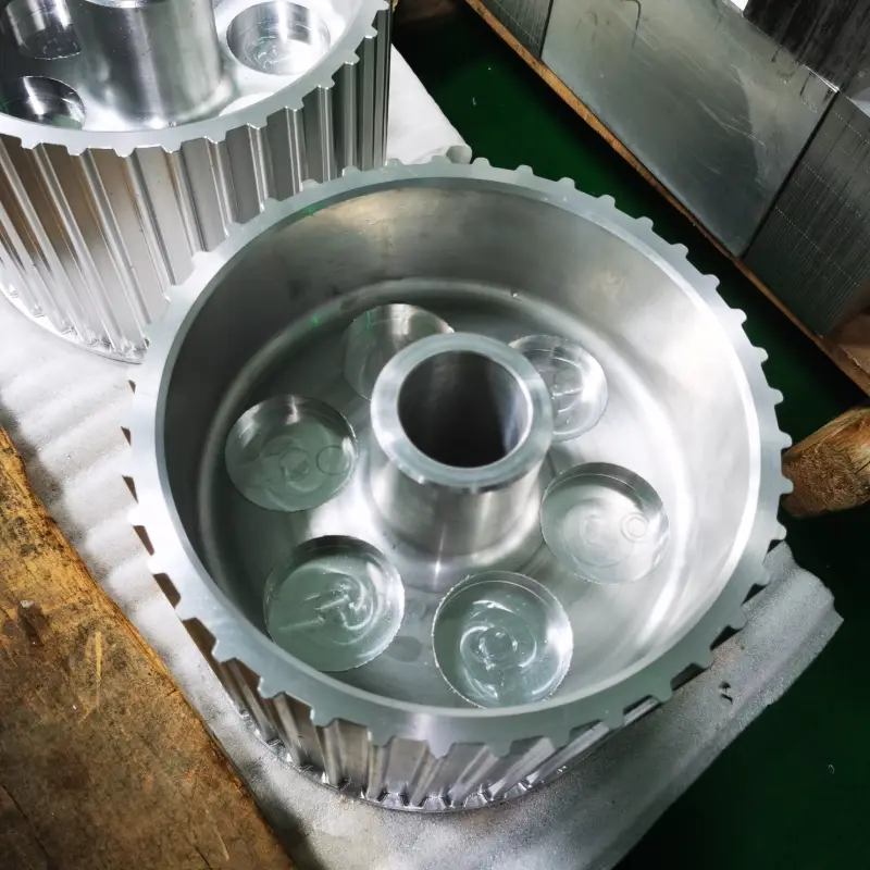
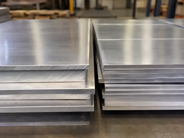
6061-T6 aluminum offers good tensile strength, yield strength, shear strength, fatigue strength, and hardness. It is commonly used for CNC-machined brackets, connectors, mounting plates, and lightweight structural parts. These properties not only determine the load-bearing capacity of a component but also affect cutting forces, tool load, clamping stability, and final dimensional accuracy.
The overall strength of 6061-T6 is higher than that of pure aluminum and many low-strength aluminum alloys, but lower than that of typical high-strength aluminum alloys and most structural steels. Its main advantage is not having the highest value in any single strength category, but achieving a practical balance between strength, weight, and machinability.
6061-T6 Aluminum Strength Data
The following values represent common typical properties of 6061-T6 aluminum. Actual results may vary depending on material thickness, product form, sampling direction, and testing standard. For production use, the supplier’s material certificate should be treated as the final reference.
| Strength Property | Typical Value |
| Ultimate Tensile Strength | Approx. 290–310 MPa |
| Yield Strength | Approx. 240–276 MPa |
| Shear Strength | Approx. 190–210 MPa |
| Fatigue Strength | Approx. 95–100 MPa |
| Brinell Hardness | Approx. 95 HBW |
MPa is the internationally accepted unit of stress, and 1 MPa equals 1 N/mm². In calculations, load is usually expressed in newtons (N) or kilonewtons (kN), while cross-sectional area is expressed in square millimeters (mm²). HBW is the standard designation for Brinell hardness and is not a stress unit.
Tensile Strength and CNC Machining
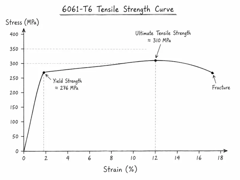
The typical ultimate tensile strength of 6061-T6 aluminum is approximately 290–310 MPa. Tensile strength represents the maximum engineering stress the material can withstand before fracturing under tension and is usually measured through a standard tensile test. During testing, a standardized specimen is pulled in a universal testing machine until fracture, while the maximum applied load is recorded.
The calculation is:
Ultimate tensile strength (MPa) = Maximum tensile load (N) ÷ Original cross-sectional area (mm²)
For example, if a specimen with an original cross-sectional area of 50 mm² reaches a maximum tensile load of 15,000 N, its ultimate tensile strength is 300 MPa.
This strength mainly comes from fine strengthening precipitates formed by magnesium and silicon. These particles are distributed throughout the aluminum matrix and restrict dislocation movement, making continuous plastic deformation more difficult. A small amount of copper can also contribute to age-hardening performance.
A tensile strength of 290–310 MPa makes 6061-T6 suitable for equipment brackets, mechanical connectors, frame components, and mounting plates under moderate loads. In CNC machining, tensile strength reflects the material’s overall resistance to tensile failure, but it cannot be used alone to predict cutting force. Actual machining load is also influenced by shear strength, hardness, tool geometry, and cutting parameters.
Yield Strength and Machining Deformation
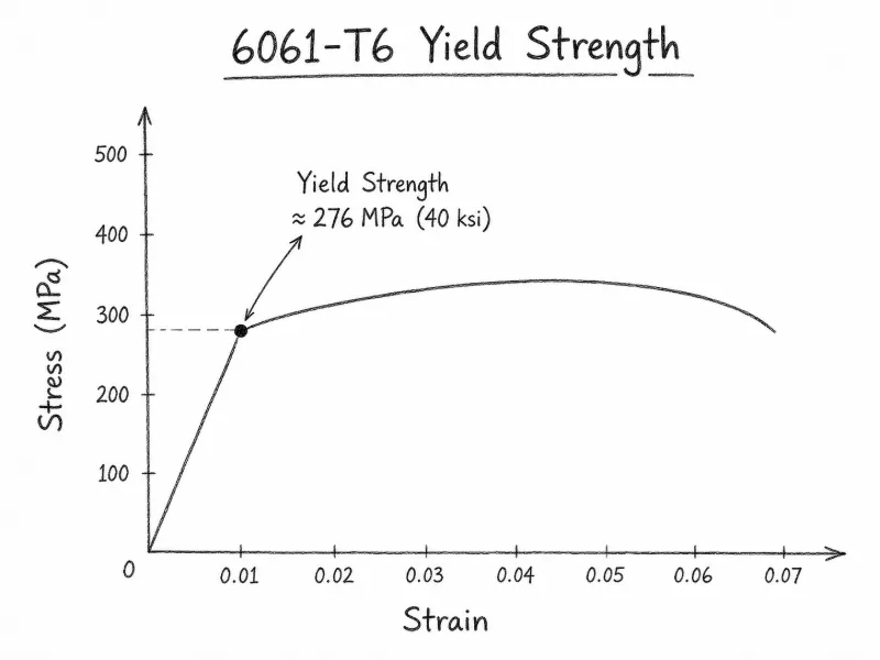
The typical yield strength of 6061-T6 aluminum is approximately 240–276 MPa. It represents the stress at which the material begins to undergo permanent plastic deformation. Because 6061-T6 usually does not show a clearly defined yield plateau, engineers commonly use the 0.2% offset method and determine the value from the stress-strain curve obtained during a tensile test.
The basic relationship is:
Yield stress (MPa) = Yield load (N) ÷ Original cross-sectional area (mm²)
For example, if a specimen with a cross-sectional area of 50 mm² reaches 0.2% permanent strain under a load of 13,000 N, the corresponding yield strength is approximately 260 MPa.
Yield strength also mainly comes from age-hardening precipitates formed by magnesium and silicon. These fine particles restrict dislocation slip, so the material must withstand a higher stress before permanent deformation begins. Insufficient artificial aging or excessive precipitate coarsening may reduce yield strength.
The relatively high yield strength helps 6061-T6 parts resist permanent deformation caused by clamping and cutting forces. This makes the material suitable for fixture bases, connecting plates, and structural components subjected to assembly loads. However, thin-walled, elongated, or locally unsupported parts may still develop dents, warping, or dimensional errors if clamping pressure becomes too concentrated.
Shear Strength and Cutting Force
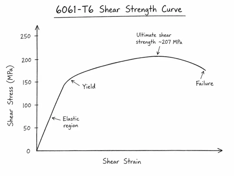
The typical shear strength of 6061-T6 aluminum is approximately 190–210 MPa. Shear strength describes the material’s ability to resist failure under parallel forces acting in opposite directions. It is usually measured using single-shear or double-shear testing.
The calculation is:
Shear strength (MPa) = Maximum shear load (N) ÷ Effective shear area (mm²)
For example, if the effective shear area is 40 mm² and the maximum shear load is 8,000 N, the shear strength is 200 MPa. In a double-shear test, there are two shear planes, so the areas of both planes must be included in the calculation.
Shear strength is influenced by the aluminum matrix, Mg₂Si strengthening precipitates, small amounts of copper, and grain structure. Fine, evenly distributed precipitates improve resistance to shear deformation, while coarse secondary-phase particles may become local crack initiation sites.
CNC cutting essentially removes material through shear deformation and separation ahead of the cutting edge. Shear strength therefore has a relatively direct relationship with cutting force, chip formation, and spindle load. When machining narrow slots, hole edges, or thin sections, a dull tool or excessive feed rate can increase burrs, edge tearing, and local deformation.
Brinell Hardness and Tool Load
The typical Brinell hardness of 6061-T6 aluminum is approximately 95 HBW, which is considered a medium-to-high level among commonly used aluminum alloys. HBW indicates that the hardness value was measured using a tungsten carbide ball indenter. It is not a stress unit such as MPa or N/mm².
During testing, a tungsten carbide ball is pressed into the material surface under a specified force. After unloading, the average indentation diameter is measured, and the hardness is calculated using the test force, ball diameter, and indentation size. Test force is expressed in newtons (N), ball and indentation diameters in millimeters (mm), and dwell time in seconds (s).
A complete result may be written as:
95 HBW 10/500/30
Where:
10 indicates a ball indenter diameter of 10 mm
500 indicates the test force level
30 indicates a dwell time of 30 s
The hardness of 6061-T6 mainly comes from fine precipitates formed by magnesium and silicon. A small amount of copper can strengthen the age-hardening response, while chromium helps control grain structure and recrystallization. Iron is not a primary strengthening element, and excessive coarse iron-silicon phases may reduce ductility and surface consistency after machining.
A hardness of approximately 95 HBW gives 6061-T6 reasonable resistance to indentation and helps maintain clean hole edges, threads, and machined profiles. In CNC machining, hardness affects tool entry and cutting-edge wear. As the tool becomes dull, the process may shift from clean shearing toward rubbing and compression, increasing built-up edge, burrs, surface tearing, and dimensional variation.
Fatigue Strength and Surface Quality
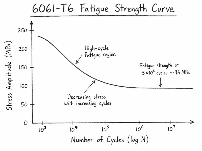
The typical fatigue strength of 6061-T6 aluminum is approximately 95–100 MPa, but this value must always be understood together with the specified number of loading cycles. Aluminum alloys generally do not have a clearly defined permanent fatigue limit, so fatigue strength should not be used without reference to cycle count.
Fatigue performance is usually measured through rotating-bending or axial cyclic loading tests. Specimens are repeatedly loaded at different stress levels, the number of cycles to failure is recorded, and an S-N curve is produced. In this curve, S represents cyclic stress in MPa, while N represents the number of cycles before fracture.
Cyclic stress can still be calculated from load and cross-sectional area:
Cyclic stress (MPa) = Cyclic load (N) ÷ Effective cross-sectional area (mm²)
Fatigue performance is influenced not only by magnesium-silicon strengthening precipitates but also by grain size, coarse secondary-phase particles, inclusions, and surface defects. Fine and evenly distributed precipitates help strengthen the matrix, while coarse particles and inclusions may become fatigue crack initiation points.
For CNC-machined components subjected to vibration, reciprocating motion, or alternating loads, deep tool marks, hole-edge burrs, scratches, and sharp corners can create stress concentrations. Therefore, 6061-T6 parts used in robotic connectors, vibration brackets, and repeatedly loaded mounting structures require careful control of finishing feed, tool runout, chamfering, and deburring quality.
How Strength Affects CNC Cutting
The different strength properties of 6061-T6 affect CNC machining in different ways. Tensile strength reflects overall load-bearing capacity, yield strength is related to permanent deformation, shear strength influences the force required to separate the material, and hardness affects tool engagement, friction, and cutting-edge wear.
Compared with pure aluminum, 6061-T6 produces higher cutting resistance, but the resistance is still significantly lower than that of steel. It is therefore well suited to high-speed CNC milling and turning. Standard structural parts usually maintain stable profiles, while thin walls, deep cavities, and long overhangs may still experience displacement, springback, or vibration because of limited local rigidity.
These strength values cannot be converted directly into fixed spindle speeds or feed rates. Actual cutting force is also influenced by tool diameter, flute count, rake angle, tool overhang, axial depth of cut, and radial width of cut.
CNC Milling Parameters for 6061-T6
When using a sharp 2- or 3-flute solid carbide end mill designed for aluminum, the following general starting parameters may be used:
| Machining Parameter | Roughing | Finishing |
| Cutting Speed | 250–600 m/min | 300–800 m/min |
| Feed per Tooth | 0.03–0.12 mm/tooth | 0.01–0.06 mm/tooth |
| Axial Depth of Cut | 0.3–1.0 × tool diameter | 0.1–0.5 mm |
| Radial Width of Cut | 10%–40% × tool diameter | 2%–10% × tool diameter |
Higher feed rates and greater cutting depths can improve material removal rates, but they also increase cutting force and tool load. When machining thin-walled, deep-cavity, or high-precision parts, reducing radial engagement and the cutting load per pass can help limit part displacement and tool deflection.
These values should only be used as starting references. Final settings should be adjusted according to tool diameter, flute count, machine rigidity, tool overhang, and clamping conditions.
Tool Selection and Lubrication
Sharp 2- or 3-flute carbide tools designed for aluminum are generally suitable for machining 6061-T6. Large chip flutes and sharp cutting edges help reduce cutting force, built-up edge, and burr formation.
Minimum quantity lubrication, or MQL, can reduce friction between the tool and workpiece while helping control tool wear and surface roughness. Related experiments indicate that feed rate and depth of cut have a significant influence on the machined surface quality of 6061-T6, while spindle speed and lubricant flow rate must also be adjusted together.
Under specific MQL test conditions, TiAlN+TiN double-layer coated carbide tools produced favorable surface roughness results. In actual production, however, tool selection should still be based on tool geometry, machine conditions, and the selected cutting parameters.
Controlling Machining Deformation
6061-T6 has relatively high yield strength, but thin-walled parts and components requiring extensive material removal may still warp because of cutting forces, clamping pressure, and changes in internal stress balance.
Common control methods include:
Applying uniform and moderate clamping pressure
Supporting thin-walled and unsupported areas
Removing material symmetrically
Separating roughing and finishing into different stages
Leaving a uniform finishing allowance
Machining critical dimensions last
The main purpose of these measures is to reduce concentrated cutting loads and limit springback and dimensional change after machining.
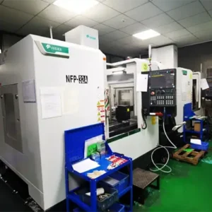
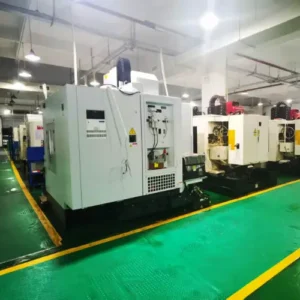
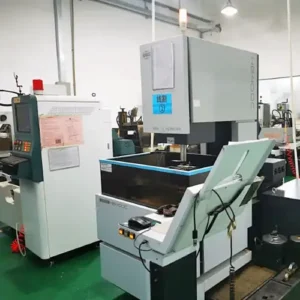
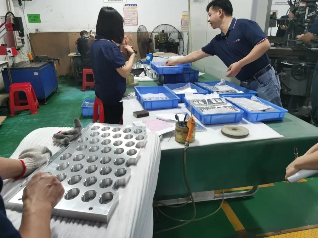
How Weldo Machining Processes 6061-T6 Parts
Weldo Machining determines the tooling, clamping method, and machining sequence according to the wall thickness, material removal volume, critical tolerances, and load requirements of each 6061-T6 component.
For thin-walled, deep-cavity, and high-flatness parts, staged material removal and low-load finishing are commonly used to reduce the influence of cutting force on dimensions and surface quality. After machining, critical dimensions, hole positions, and surface roughness can be inspected against the drawing requirements.
Conclusion
The tensile strength, yield strength, shear strength, fatigue strength, and hardness of 6061-T6 allow it to meet the load requirements of many lightweight structural components while maintaining good CNC machinability.
In practical machining, shear strength and hardness mainly affect cutting force and tool load, yield strength relates to permanent deformation, and fatigue strength is closely connected to machined surface integrity. Appropriate control of tooling, cutting parameters, clamping, and machining sequence is necessary to make full use of the strength advantages of 6061-T6 aluminum.