
What Is Surface Roughness ?
Surface roughness is an important indicator used to measure the microscopic peaks and valleys on a part surface. It is not simply about whether a part “looks smooth.” Instead, it uses parameters such as Ra and Rz to quantify tool marks, peaks, valleys, and fine surface textures.
In CNC machining, surface roughness can affect assembly accuracy, friction, wear resistance, sealing performance, surface finishing results, and service life. For example, a standard mounting bracket may not need a very fine surface. However, sealing surfaces, sliding surfaces, visible surfaces, and anodized parts often require tighter surface roughness control.
From a machining and quality inspection perspective, defining surface roughness requirements early helps the manufacturer choose suitable tools, cutting parameters, tool paths, and inspection methods. This can reduce rework, extra cost, and delivery delays. If a drawing only says “smooth surface” or “fine finish,” the machine shop may not be able to judge the real requirement accurately.
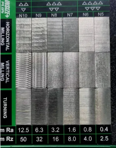
Surface Roughness Chart
In CNC machining projects, surface roughness is usually defined by Ra values. A lower Ra value usually means a finer surface. However, this does not mean every part should use the lowest possible Ra. A finer surface often requires slower machining, stricter inspection, and sometimes grinding, polishing, or other secondary finishing processes.
The following surface roughness chart can be used as a common reference for CNC machined parts. Actual results may vary depending on material, cutting tools, equipment, fixturing, machining parameters, and post-processing methods.
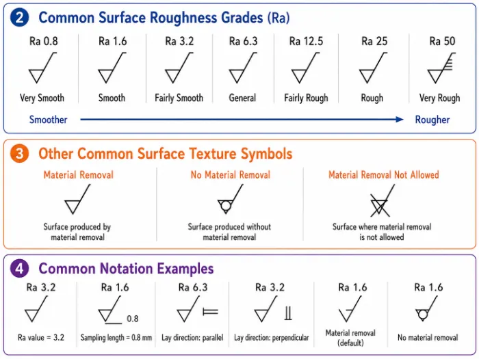
| Ra Value Range | Surface Level | Common Machining Process | Typical Applications |
|---|---|---|---|
| Ra 6.3 μm | Rough machined surface | Rough milling, rough turning, general material removal | Non-critical structural parts, internal supports, pre-machined blank surfaces |
| Ra 3.2 μm | Standard machined surface | General CNC milling and turning | Brackets, housings, frames, general assembly parts |
| Ra 1.6 μm | Fine machined surface | Finish milling, finish turning, optimized tool paths | Visible surfaces, assembly surfaces, aluminum housings, exposed parts |
| Ra 0.8 μm | Precision machined surface | Fine machining, grinding, controlled tool marks | Sealing surfaces, sliding surfaces, mating surfaces, precision mechanical parts |
| Ra 0.4 μm or lower | High-precision surface | Grinding, polishing, superfinishing | Mold components, optical parts, high-precision mating parts |
Note: Surface roughness values are often shown in micrometers (μm) or microinches (μin). The conversion is: 1 μin = 0.0254 μm. For example, 32 μin ≈ 0.8 μm, and 63 μin ≈ 1.6 μm.
What Is the Difference Between Ra and Rz?
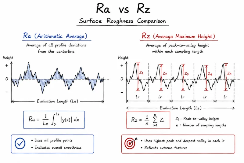
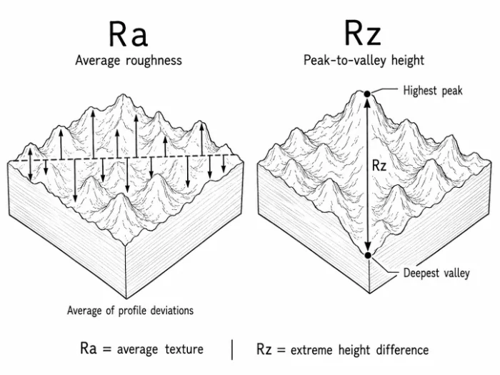
Ra and Rz are two of the most common surface roughness parameters. In simple terms, Ra looks at the average surface level, while Rz looks at the difference between the highest peaks and deepest valleys.
What Is Ra?
- Ra is the average roughness
Ra measures the average deviation of the surface profile from the centerline within a sampling length. It shows how rough the overall surface is on average. - Ra is useful for judging general surface smoothness
Common drawing values include Ra 3.2, Ra 1.6, and Ra 0.8. The smaller the value, the finer the surface usually is. - Ra is the most commonly used roughness parameter on CNC drawings
For general structural parts, housings, brackets, panels, and standard appearance parts, Ra is usually enough for machining and inspection.
What Is Rz?
- Rz focuses more on peak-to-valley height
Rz mainly reflects the height difference between higher peaks and deeper valleys on the surface profile. It is more sensitive to local tool marks, scratches, sharp peaks, and deep grooves. - Rz is better for controlling critical functional surfaces
If a part is used for sealing, sliding, friction, rotation, or long-term loading, Ra alone may not be enough. Even when the average roughness is acceptable, local deep marks or peaks may still affect sealing, wear resistance, or fatigue life. - Rz is often used in stricter quality control applications
Sealing surfaces, bushings, slide blocks, guide rails, hydraulic parts, and precision mating surfaces often require close attention to Rz.
For most standard CNC machined parts, specifying Ra on the drawing is usually enough. However, if the part involves sealing, sliding, friction, precision mating, or long-term loading, both Ra and Rz should be considered.
How to Understand Surface Roughness Symbols on Drawings?
In CNC machining drawings, a surface roughness symbol tells the manufacturer what surface quality is required for a specific area. For engineers, it is a design requirement. For machine shops, it affects tool selection, machining process, inspection method, and final quotation.
What Information Does a Surface Roughness Symbol Usually Include?
- Roughness parameter
Ra is the most common parameter. Some precision parts may also specify Rz. - Roughness value
Common examples include Ra 3.2, Ra 1.6, and Ra 0.8. A smaller value usually means a higher surface requirement. - Machining requirement
Some drawings may also specify whether machining, grinding, polishing, or a certain lay direction is required.
Why Should Surface Roughness Be Clearly Marked on Drawings?
Clear drawing notes can reduce misunderstandings between the customer and the machine shop. They also help lower the risk of rework, returns, and delivery delays. For example, if a customer only requests a “smooth surface” without a specific Ra value, the manufacturer may use a standard machined finish. That finish may not meet the needs of appearance parts, sealing parts, or anodized components.
On the other hand, specifying very strict roughness requirements on non-critical surfaces can increase machining time, inspection cost, and delivery pressure. Therefore, customers should separate functional surfaces, visible surfaces, and non-critical surfaces on the drawing. Each surface should have a reasonable roughness requirement based on its actual use.
How Does Surface Roughness Affect CNC Machined Parts?
Many buyers focus mainly on dimensional tolerances. However, surface roughness is also important. Even if the dimensions are correct, a part may still fail during assembly, sealing, movement, or surface finishing if the surface quality is not suitable.
Effect on Assembly Accuracy
Excessive roughness can reduce contact quality between mating surfaces. Precision assembly parts may have uneven clearance, unstable positioning, or poor assembly feel.
Effect on Friction and Wear
If the surface of a sliding, rotating, or guiding part is too rough, friction will increase. This can speed up wear. A suitable Ra or Rz value helps improve movement stability and service life.
Effect on Sealing Performance
If a sealing surface has deep tool marks, scratches, or excessive peak-to-valley height, leakage or unstable sealing may occur. Hydraulic parts, pneumatic parts, valve bodies, and sealing components usually need stricter roughness control.
Effect on Appearance and Surface Finishing
The results of anodizing, sandblasting, electroplating, polishing, or coating depend heavily on the CNC machined surface before finishing. If the original surface has obvious tool marks, scratches, or clamping marks, post-processing may not fully hide them. In some cases, it may make the defects more visible.
Effect on Cost and Lead Time
A lower Ra value usually means finer machining, stricter inspection, and longer machining time. Choosing a surface roughness that matches the part’s real function is more cost-effective than always asking for the lowest Ra. It also helps control lead time.
What Are the Common Tools for Measuring Surface Roughness?
In CNC quality inspection, surface roughness cannot be confirmed only by visual checks or touch. It needs to be verified with proper measuring tools. The right tool depends on the part’s accuracy requirement, surface condition, material, and inspection environment.
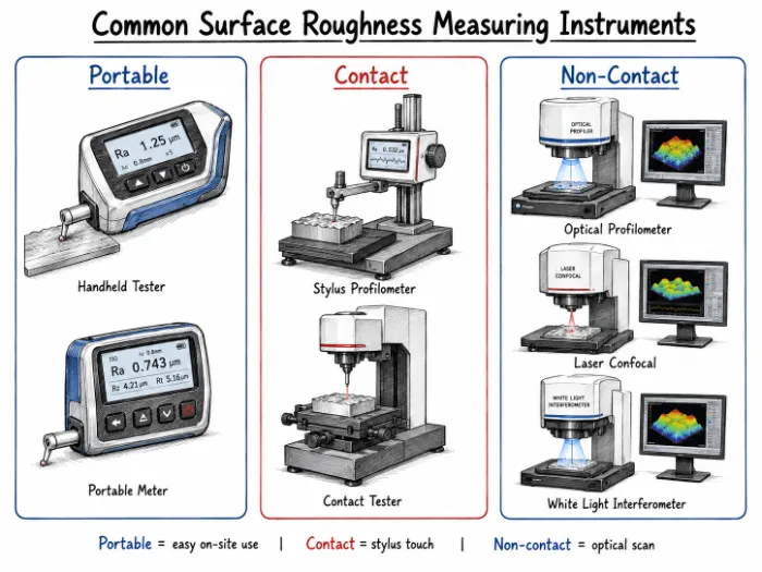
Contact Surface Roughness Tester
A contact surface roughness tester is the most common tool used in CNC machining. It usually uses a probe to move across the part surface. The probe collects microscopic profile data and calculates parameters such as Ra and Rz. This tool is suitable for most machined metal and plastic parts. It can be used for first article inspection, in-process inspection, and final inspection. Portable roughness testers also belong to this category. They are useful for shop-floor checks and large parts.
Profilometer
A profilometer records a more complete surface profile curve. It can be used for roughness analysis and surface profile observation. Compared with a standard roughness tester, a profilometer is more suitable for sealing surfaces, sliding surfaces, precision mating surfaces, and other functional areas with higher surface requirements.
Non-Contact Optical Measuring Equipment
Non-contact measuring equipment usually uses laser, white light interferometry, confocal technology, or other optical methods. It does not require a probe to touch the part surface. It is suitable for mirror-like parts, coated surfaces, soft materials, delicate surfaces, and micro-structured parts. However, this type of equipment is more expensive. It is not as common as contact roughness testers for standard CNC machined parts.
Surface Roughness Comparator
A surface roughness comparator is mainly used for quick shop-floor comparison. It is commonly used to compare milling, turning, grinding, and other machining textures. It cannot provide precise Ra or Rz values. It also cannot replace a formal inspection report. However, it is useful for discussing surface appearance, checking machining textures, and making an initial quality judgment.
What Factors Affect Surface Roughness in CNC Machining?
Surface roughness in CNC machining is mainly affected by tool condition, cutting parameters, material properties, machine stability, and fixturing. For parts that require controlled Ra or Rz, surface quality should not rely only on final inspection. It should be considered during process planning.
Tool Condition
Tool sharpness and tool wear directly affect the machined surface. A worn tool can create burrs, scratches, built-up edge, and obvious tool marks. This increases the Ra value. For softer materials such as aluminum and copper alloys, built-up edge should be controlled. For difficult materials such as stainless steel and titanium, tool wear and cutting heat must be managed carefully.
Cutting Parameters
Cutting speed, feed rate, and depth of cut are key factors. If the feed rate is too high, tool marks become more visible. If cutting speed is not suitable, chatter marks or surface tearing may appear. During finishing, more stable cutting parameters are usually needed to achieve a more uniform surface.
Material Properties
Different materials behave differently during machining. Aluminum alloys usually achieve a better surface finish more easily, but they may stick to the tool or scratch easily. Stainless steel has high toughness and may cause work hardening or surface tearing. Engineering plastics need attention to heat deformation and edge fuzzing. Material selection affects the achievable roughness level and machining cost.
Machine and Fixturing Stability
Poor machine rigidity or unstable fixturing can cause vibration. This may lead to chatter marks, surface waves, and dimensional variation. Fixture design is especially important for thin-wall parts, long shafts, deep cavities, and irregular parts. Proper clamping can reduce deformation and vibration, making surface roughness more stable.
How to Choose the Right Surface Roughness for a CNC Project?
When choosing surface roughness, the goal should not be the lowest Ra value. The right choice should be based on part function, assembly requirements, appearance needs, surface finishing method, and budget. Overly strict roughness requirements can increase machining time, inspection cost, and delivery pressure. Requirements that are too loose may affect part performance and service life.
Separate Critical and Non-Critical Surfaces
Different surfaces on the same part may need different roughness levels. Sealing surfaces, sliding surfaces, mating surfaces, and visible surfaces usually require tighter Ra or Rz control. Internal clearance surfaces, non-contact surfaces, and standard structural surfaces can often use a general machined finish. This helps control cost while still meeting functional requirements.
Choose Ra Values Based on Part Function
Standard brackets, frames, and internal structural parts can usually use Ra 3.2 μm or Ra 6.3 μm. Appearance parts, housings, and panels often use Ra 1.6 μm or Ra 3.2 μm. Sealing surfaces, sliding surfaces, and precision mating surfaces may require Ra 0.8 μm or a finer finish.
Consider the Final Surface Treatment
If the part needs anodizing, sandblasting, polishing, electroplating, or coating, the CNC machined surface before finishing will affect the final result. Obvious tool marks, scratches, or clamping marks may become more visible after finishing. For appearance parts and surface-treated parts, roughness requirements should be defined early.
Clarify Requirements Before Quotation
To get a more accurate quote and lead time, it is best to provide drawings, material, quantity, tolerances, Ra/Rz requirements, surface finishing requirements, and delivery timeline. If the drawing only says “smooth surface” or “fine finish,” the requirement can be misunderstood. Clear surface roughness requirements help the manufacturer evaluate process, cost, and delivery more accurately.
How to Control Surface Roughness on CNC Machined Parts?
In real CNC machining, surface roughness control depends not only on machine accuracy, but also on process experience. A qualified machining manufacturer will review the Ra, Rz, material, tolerance, and surface finishing requirements on the customer’s drawing. If needed, the manufacturer will confirm possible adjustments with the customer. Then the team will choose suitable cutting tools, machining parameters, fixturing methods, and inspection methods to achieve a more stable surface finish.
For aluminum, stainless steel, copper alloys, engineering plastics, and other materials, we provide practical machining advice based on part function and surface requirements. For example, appearance parts need careful control of tool marks and scratches. Sealing surfaces need better peak-to-valley control. Anodized parts need consistent machined surfaces before finishing. Through in-process checks and final inspection, roughness issues, surface scratches, and post-processing defects can be reduced.
Summary
Surface roughness is a key quality factor in CNC machining. It affects not only part appearance, but also assembly accuracy, friction, sealing performance, surface finishing, cost, and delivery time. Understanding Ra, Rz, surface roughness symbols, roughness charts, and measurement methods helps buyers define machining requirements more clearly and avoid unnecessary quality disputes.
For CNC machined parts, the right surface roughness is not always the lowest Ra value. It is the value that best matches the part’s function, material, finishing process, and budget. If you need CNC parts with controlled surface roughness, Weldo Machining can help review your drawings, recommend practical Ra/Rz requirements, and provide transparent quotes based on your material, tolerance, surface finish, quantity, and delivery timeline.