Why Do Engineers Use ISO 2768?
As engineers, we constantly balance part functionality with budget constraints. Every tight tolerance you add to a print drives up the manufacturing price. We rely on ISO 2768 to establish a practical baseline for general tolerance standards. It keeps our parts functional without forcing us to pay for unnecessary accuracy.
Machining Cost Optimization: Cost vs. Precision
Tight tolerances demand slower machining feeds, extra setups, and specialized inspection tools. This ruins any attempt at machining cost optimization. By applying standard metric tolerances, you give the shop a clear, achievable target for standard features.
We use these standardized benchmarks to keep budgets under control:
- Prevent Over-Engineering: Establish a baseline for CNC machining tolerances so machinists do not waste time chasing perfection on non-critical features.
- Lower Production Costs: You only pay for high-precision operations on the specific surfaces that actually require it.
- Faster Quoting: Shops can quote parts faster when they see standard drawing specifications rather than custom constraints on every dimension.
Engineering Drawing Simplification
Nobody wants to decipher a crowded, messy print. Specifying an individual tolerance for every single length, width, and hole creates cluttered engineering drawing specifications. It increases the chance of a misread dimension on the shop floor.
Applying a global standard cleans up your drawings instantly. We simply drop the standard callout into the title block, and it automatically covers all non-critical linear and angular dimensions. This speeds up the initial drafting process and drastically reduces the machinist’s review time before production begins.
ISO 2768-1: Linear and Angular Dimensions
When we review an engineering print on the shop floor, ISO 2768-1 is our baseline for controlling linear and angular dimensions. Instead of cluttering the drawing with custom callouts for every single cut, we rely on these general tolerance standards to streamline the build and keep your machining costs under control.
Tolerance Class f m c v
ISO 2768-1 breaks down into four specific tolerance grades. We match these classes to the machining part accuracy required for your specific application:
- f (Fine): The tightest general tolerance. We reserve this for high-precision components where fit and function are highly critical.
- m (Medium): The industry standard. A medium tolerance is our everyday default for standard CNC machining tolerances.
- c (Coarse): Looser limits, ideal for non-critical features where you want to cut down on production time and save money.
- v (Very Coarse): Extremely loose constraints, typically used for rough cuts, raw material sizing, or clearance holes.
Linear Dimensions Tolerance Table
Here is a straightforward look at the metric tolerances (in millimeters) we hold for standard linear sizes.
| Nominal Size Range (mm) | Fine (f) | Medium (m) | Coarse (c) | Very Coarse (v) |
|---|---|---|---|---|
| 0.5 to 3 | ± 0.05 | ± 0.1 | ± 0.2 | – |
| Over 3 to 6 | ± 0.05 | ± 0.1 | ± 0.3 | ± 0.5 |
| Over 6 to 30 | ± 0.1 | ± 0.2 | ± 0.5 | ± 1.0 |
| Over 30 to 120 | ± 0.15 | ± 0.3 | ± 0.8 | ± 1.5 |
| Over 120 to 400 | ± 0.2 | ± 0.5 | ± 1.2 | ± 2.5 |
External Radii and Chamfer Heights Table
For broken edges, fillets, and chamfers, our drawing specifications scale a bit differently to ensure safe part handling and proper assembly.
| Nominal Size Range (mm) | Fine (f) & Medium (m) | Coarse (c) & Very Coarse (v) |
|---|---|---|
| 0.5 to 3 | ± 0.2 | ± 0.4 |
| Over 3 to 6 | ± 0.5 | ± 1.0 |
| Over 6 | ± 1.0 | ± 2.0 |
Angular Dimensions Tolerance Table
Angles require a slightly different approach because the tolerance actually tightens depending on the length of the shortest side forming that angle.
| Length of Shortest Side (mm) | Fine (f) & Medium (m) | Coarse (c) | Very Coarse (v) |
|---|---|---|---|
| Up to 10 | ± 1° | ± 1° 30′ | ± 3° |
| Over 10 to 50 | ± 0° 30′ | ± 1° | ± 2° |
| Over 50 to 120 | ± 0° 20′ | ± 0° 30′ | ± 1° |
ISO 2768-2: Geometrical Tolerances (Part 2)
While the first part of the ISO 2768 standard focuses on linear and angular size, ISO 2768-2 steps in to control the actual shape, position, and orientation of the features on your part. When we machine components for our US customers, we rely on these general tolerance standards to ensure parts stay flat, straight, and true without cluttering the engineering drawing specifications with redundant callouts.
The Three Tolerance Classes (H, K, L)
To balance machining part accuracy with cost, ISO 2768-2 categorizes geometrical tolerances into three specific classes. Selecting the right class dictates how tightly the geometry is controlled.
- Class H (Fine): The tightest geometrical control, reserved for precision assemblies.
- Class K (Medium): The standard baseline for most general CNC machining tolerances. It provides a solid balance of quality and cost.
- Class L (Coarse): Best for non-critical features where geometric perfection is not required.
Geometrical Tolerance Tables
The geometrical tolerances under this standard cover several key characteristics. Here is a breakdown of the standard metric tolerances applied based on the nominal length of the feature.
Table 1: Straightness and Flatness Tolerances (mm)
| Nominal Length Range (mm) | Class H (Fine) | Class K (Medium) | Class L (Coarse) |
|---|---|---|---|
| Up to 10 | 0.02 | 0.05 | 0.1 |
| Over 10 to 30 | 0.05 | 0.1 | 0.2 |
| Over 30 to 100 | 0.1 | 0.2 | 0.4 |
| Over 100 to 300 | 0.2 | 0.4 | 0.8 |
Table 2: Perpendicularity Tolerances (mm)
| Nominal Length Range (mm) | Class H (Fine) | Class K (Medium) | Class L (Coarse) |
|---|---|---|---|
| Up to 100 | 0.2 | 0.4 | 0.6 |
| Over 100 to 300 | 0.3 | 0.6 | 1.0 |
| Over 300 to 1000 | 0.4 | 0.8 | 1.5 |
Table 3: Symmetry Tolerances (mm)
| Nominal Length Range (mm) | Class H (Fine) | Class K (Medium) | Class L (Coarse) |
|---|---|---|---|
| Up to 100 | 0.5 | 0.6 | 0.6 |
| Over 100 to 300 | 0.5 | 0.6 | 1.0 |
| Over 300 to 1000 | 0.5 | 0.8 | 1.5 |
Note: For characteristics like concentricity and run-out, ISO 2768-2 also defines strict boundaries (e.g., Run-out is 0.1mm for H, 0.2mm for K, and 0.5mm for L across all lengths). Using these tables streamlines the design process. Instead of defining the flatness or perpendicularity on every single edge, calling out ISO 2768-2 ensures the entire part is held to a reliable, standardized baseline.
Decoding ISO 2768-mK Meaning
When reviewing engineering drawing specifications, you will frequently see the callout “ISO 2768-mK” tucked into the title block. If you are handling metric tolerances, this code is your baseline. I deal with these prints every day in our machine shop, and it is simply a shorthand way to define the general tolerance standards for the entire part without cluttering the print with redundant numbers.
Here is exactly how to break down the ISO 2768-mK meaning:
- ISO 2768: The baseline global standard governing the part’s general tolerances.
- “m” (Linear and Angular Dimensions): This lowercase letter links directly to ISO 2768-1. Out of the linear tolerance class f m c v (fine, medium, coarse, very coarse), the “m” stands for medium. This is the standard, cost-effective expectation for typical CNC machining tolerances.
- “K” (Geometrical Tolerances): This uppercase letter links to ISO 2768-2. It sets the baseline rules for shapes, such as straightness, flatness, and symmetry. The “K” represents the standard, medium accuracy class for these geometric forms.
Quick Breakdown of the Callout
| Callout Part | Refers To Standard | Covers | Accuracy Class |
|---|---|---|---|
| m | ISO 2768-1 | Linear & Angular Dimensions | Medium |
| K | ISO 2768-2 | Geometrical Tolerances | Medium |
By combining these two letters into one quick “mK” label, engineers keep the blueprint clean while giving our manufacturing team clear, reliable boundaries for part accuracy.
ISO 2768 vs GD&T: When to Use Which?
In our shop, deciding between ISO 2768 vs GD&T usually comes down to one simple question: how critical is the feature to the final assembly?
While ISO 2768 provides a reliable baseline for general tolerance standards, GD&T (Geometric Dimensioning and Tolerancing) steps in when precision is absolutely non-negotiable. Here is how we break it down to balance machining part accuracy with machining cost optimization:
When to Use ISO 2768
- Non-Critical Features: Best for everyday dimensions that do not impact how the part operates or fits.
- Cost Control: Relies on standard CNC machining tolerances, which speeds up production runs and lowers overall costs.
- Drawing Simplicity: Keeps your engineering drawing specifications clean and easy to read by eliminating redundant callouts.
When to Use GD&T
- Critical Interfaces: Mandatory for mating parts, complex assemblies, or strict clearance requirements.
- Tight Geometric Control: Dictates exact shapes and forms (like true position, flatness, or concentricity) that go beyond basic linear and angular dimensions.
- High-Stakes Precision: Necessary when part functionality demands absolute accuracy, even if it requires specialized inspection and drives up manufacturing costs.
If a dimension does not make or break the part, we recommend defaulting to the ISO 2768 standard. If a specific feature dictates the success of the entire assembly, apply GD&T to lock down those critical tolerances.
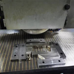
Flange machining project
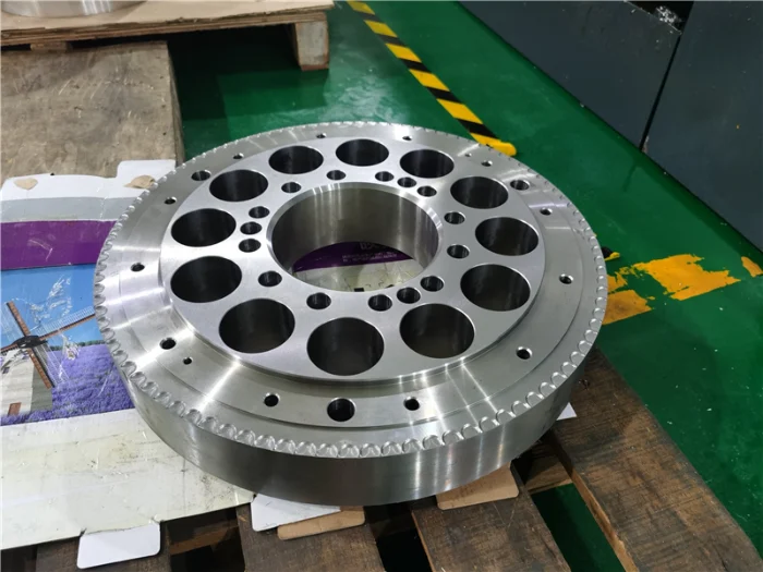
In a typical cnc machining project, we were tasked with manufacturing an stainless steel flange used for pipeline connections. The part was made from 6061-T6 and included several key features on the drawing: an outer diameter of Ø120 mm, an inner bore of Ø60 mm, a thickness of 12 mm, and six evenly spaced bolt holes of Ø11 mm on a pitch circle diameter (PCD) of Ø90 mm. The inner bore, serving as a critical mating feature, was specified with an H7 tolerance, and the bolt hole positions had basic assembly requirements. However, dimensions such as the outer diameter, chamfers, thickness, and other non-critical features were not individually toleranced—something we frequently see in real-world engineering drawings.
In this case, we applied ISO 2768-mK in the title block as the general tolerance standard. This means all unspecified linear dimensions follow the medium (m) tolerance class defined in ISO 2768-1, while geometrical tolerances follow the K class in ISO 2768-2. For example, the Ø120 mm outer diameter would fall within an approximate range of ±0.3 to ±0.5 mm, and the 12 mm thickness would be controlled around ±0.2 mm. At the same time, overall flatness, perpendicularity, and other geometric characteristics are governed by a consistent baseline. This approach significantly reduces drawing clutter and ensures that programming, machining, and inspection teams are aligned on achievable and standardized tolerances.
From an engineering perspective, this method effectively balances precision and cost. Critical features are tightly controlled through specific tolerances or GD&T, while non-critical features rely on ISO 2768 to avoid unnecessary machining effort and cost. Based on this flange case, we can further explore how ISO 2768 is applied in real manufacturing scenarios and how it helps achieve an optimal balance between functionality, efficiency, and cost-effectiveness.
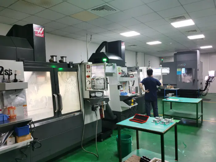
Manufacturing to ISO 2768 Standards at Weldo Machining
At Weldo Machining, we know that balancing machining part accuracy with your budget is critical. That is why we strictly rely on ISO 2768 general tolerance standards for our everyday production runs. Unless your engineering drawing specifications demand highly specialized GD&T, we apply these standard tolerances in manufacturing to keep your project efficient and highly cost-effective.
Here is exactly how we handle metric tolerances on our shop floor:
- Optimal Precision: We consistently machine parts to the widely used ISO 2768-mK standard, hitting the perfect sweet spot for medium linear and geometrical tolerances.
- Machining Cost Optimization: By standardizing manufacturing expectations, we eliminate unnecessary CNC setups, speed up production times, and drastically reduce scrap rates.
- Guaranteed Quality: Our inspection team rigorously verifies all linear and angular dimensions against official tolerance charts before any component ships out to your US facility.
We have the advanced CNC equipment and the specialized expertise to execute your exact drawing specifications. You can contact with us later to get fast quote..