
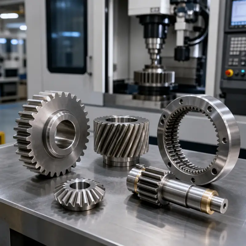
Custom Gear Manufacturing
Custom Gears Built Around Your Drawing
Drawing-based metal and engineering-plastic gears for prototypes, low-volume orders and repeat production. Send the tooth data, material, operating conditions and inspection requirements for an engineering review and transparent quote.
Heat treatment, surface finishing and inspection are coordinated through one production route.
Upload Your Gear Drawing →Gear Structures
Gear Types for Different Motion Systems
Select the closest structure, then define tooth data, shaft arrangement, interfaces, load, speed, lubrication and required accuracy.
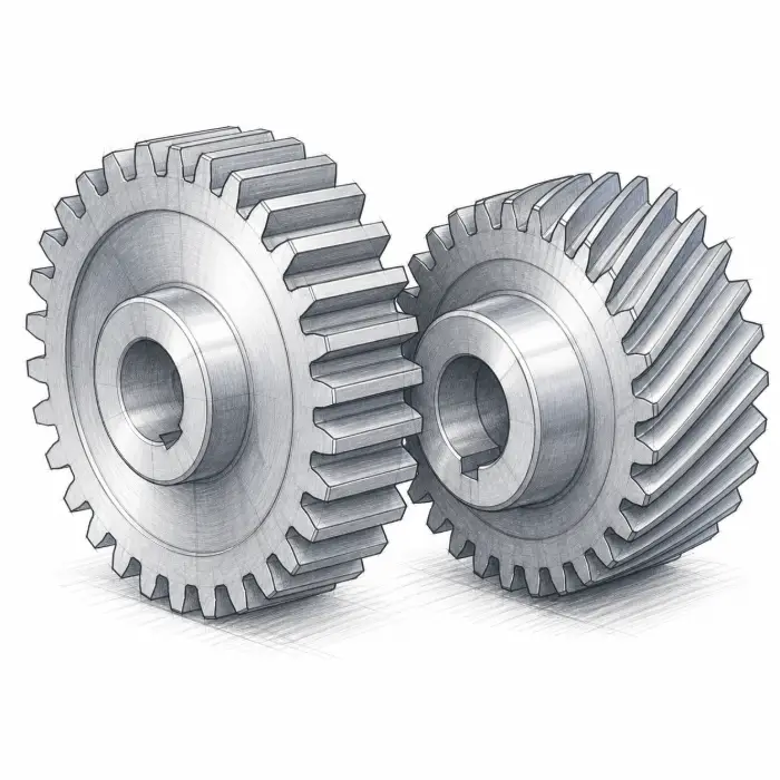
Spur & Helical Gears
External gears for parallel-axis drives, from direct engagement to smoother helical motion.
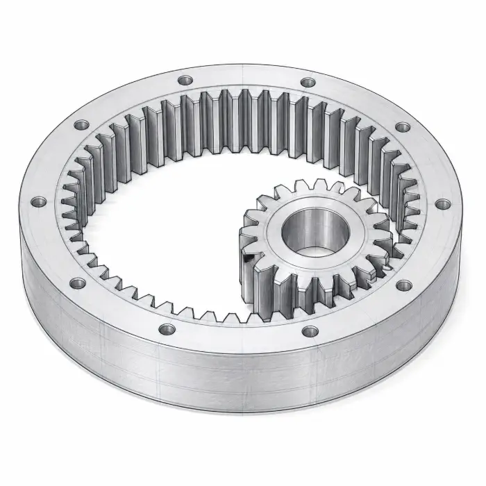
Internal & Ring Gears
Compact internal-tooth and annular structures for planetary and circular assemblies.
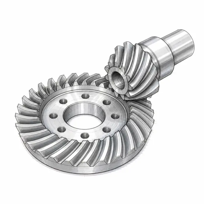
Bevel Gears
Angle-drive gears for intersecting or offset shaft arrangements.
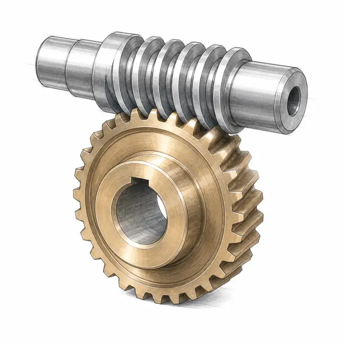
Worm Gears
High-ratio worm and wheel sets for skew-axis transmission.
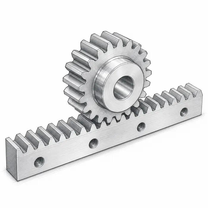
Gear Racks
Linear tooth elements paired with pinions for controlled travel.
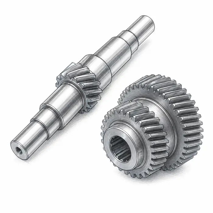
Gear Shafts & Compound Gears
Integrated teeth, shafts, hubs and multiple stages with controlled datum relationships.
Material Selection
Gear Materials, Grades and Treatments
Choose metal or engineering plastic first, then compare grades by tooth strength, fatigue life, wear, corrosion, lubrication and dimensional stability.
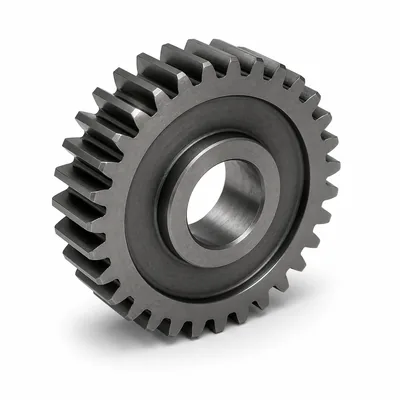
Alloy & Case-Hardening Steel
High tooth strength, fatigue resistance and heat-treatment flexibility for load-bearing gears.
- Common Grades
- 1045, 4140, 4340, 8620 and compatible gear steels.
- Service Environment
- General transmission, gear shafts and high-load drives.
- Treatment & Finish
- Carburizing, nitriding, induction or through hardening; black oxide or phosphate when specified.
- Selection Basis
- Load, speed, lubrication, temperature, corrosion and dimensional stability.
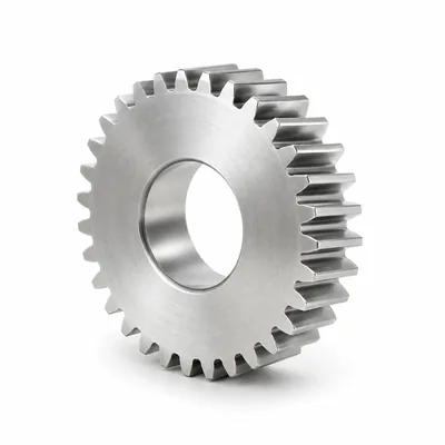
Stainless Steel
Corrosion resistance and cleanliness for moisture, washdown and chemical exposure.
- Common Grades
- 303, 304, 316L, 420 and 17-4 PH.
- Service Environment
- Food, medical, marine, chemical and clean-service equipment.
- Treatment & Finish
- Passivation or electropolishing; hardening only for compatible grades.
- Selection Basis
- Load, speed, lubrication, temperature, corrosion and dimensional stability.
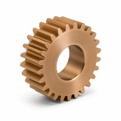
Bronze
Anti-galling and sliding-wear behavior for worm wheels and friction-sensitive pairs.
- Common Grades
- C93200, C95400, C95500 and project-specific bronzes.
- Service Environment
- Worm drives, lubricated motion and heavy-duty sliding contact.
- Treatment & Finish
- Machined finish or controlled polishing; heat treatment depends on alloy condition.
- Selection Basis
- Load, speed, lubrication, temperature, corrosion and dimensional stability.
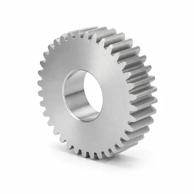
Aluminum
Low rotating mass and corrosion resistance for moderate-load lightweight mechanisms.
- Common Grades
- 6061-T6, 6082-T6, 7075-T6 and MIC-6 where appropriate.
- Service Environment
- Robotics, instruments and low-inertia drive systems.
- Treatment & Finish
- Anodizing or hard anodizing when compatible with fit and wear requirements.
- Selection Basis
- Load, speed, lubrication, temperature, corrosion and dimensional stability.
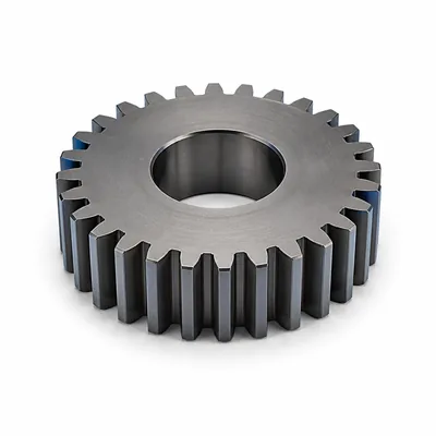
Titanium & Nickel Alloys
High specific strength, corrosion resistance or elevated-temperature capability for specialized gears.
- Common Grades
- Ti-6Al-4V and drawing-specified titanium or nickel-alloy grades.
- Service Environment
- Aerospace, chemical, high-temperature and regulated equipment.
- Treatment & Finish
- Alloy-compatible treatments confirmed from the drawing and governing specification.
- Selection Basis
- Load, speed, lubrication, temperature, corrosion and dimensional stability.
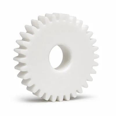
POM / Acetal
Low friction, stable dimensions and quiet motion for light-to-moderate loads.
- Common Grades
- POM-C, POM-H and filled acetal grades.
- Service Environment
- Instruments, automation, small drives and low-noise mechanisms.
- Treatment & Finish
- As-machined with controlled deburring; avoid excessive post-machining heat.
- Selection Basis
- Load, speed, lubrication, temperature, corrosion and dimensional stability.
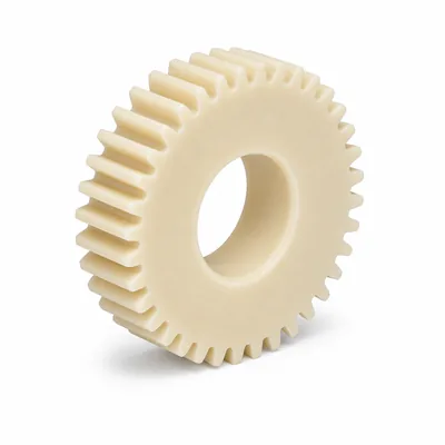
PA / Nylon
Toughness, wear resistance and impact tolerance with moisture-aware clearance design.
- Common Grades
- PA6, PA66, PA12, MC Nylon and reinforced grades.
- Service Environment
- Conveyors, machinery, moderate-load gears and impact-prone mechanisms.
- Treatment & Finish
- As-machined or lightly polished; moisture conditioning only when specified.
- Selection Basis
- Load, speed, lubrication, temperature, corrosion and dimensional stability.
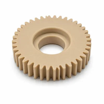
PEEK
High-temperature strength and chemical resistance for demanding precision mechanisms.
- Common Grades
- Virgin, glass-filled, carbon-filled and bearing grades.
- Service Environment
- Aerospace, medical, semiconductor and chemical equipment.
- Treatment & Finish
- As-machined; annealing may be specified for dimensional stability.
- Selection Basis
- Load, speed, lubrication, temperature, corrosion and dimensional stability.
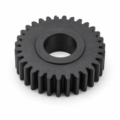
UHMW-PE / PTFE Compounds
Low-friction polymers selected for wear, chemical and electrical requirements.
- Common Grades
- UHMW-PE and application-specific filled PTFE compounds.
- Service Environment
- Low-load guides, sprockets and chemically exposed or electrically insulating mechanisms.
- Treatment & Finish
- As-machined or lightly deburred; resin-compatible conditioning only when specified.
- Selection Basis
- Load, speed, lubrication, temperature, corrosion and dimensional stability.
Final grade, supplied condition, hardness and treatment are confirmed against the drawing and operating requirements.
Drawing-Based Capability
Custom Gear Manufacturing Parameters
These ranges support quotation review and are not guaranteed limits for every geometry and material combination.
| Capability | Review Range | Key Requirement |
|---|---|---|
| Module | M0.3–M12 | Tooth form and inspection method |
| Gear diameter | Ø8–Ø1,200 mm | Structure, blank and machine access |
| Tooth count | 6–500 teeth | Module, profile and diameter |
| Face width | 2–300 mm | Tool access and rigidity |
| Pressure angle | 14.5° · 20° · 25° | Drawing and mating gear |
| Helix angle | Up to 45° | Hand, lead and inspection |
| Target accuracy | ISO 1328 Grade 5–10 | Confirmed from geometry and verification method |
Final capability depends on gear type, size, material condition, heat treatment, tooth form, datum scheme and inspection method.
Manufacturing and Inspection
From Gear Drawing Review to Protected Delivery
The production route is planned around datum control, tooth generation, treatment timing and inspection checkpoints.
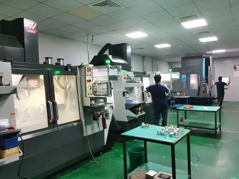
Confirm tooth data, material, treatment, quantity and records.
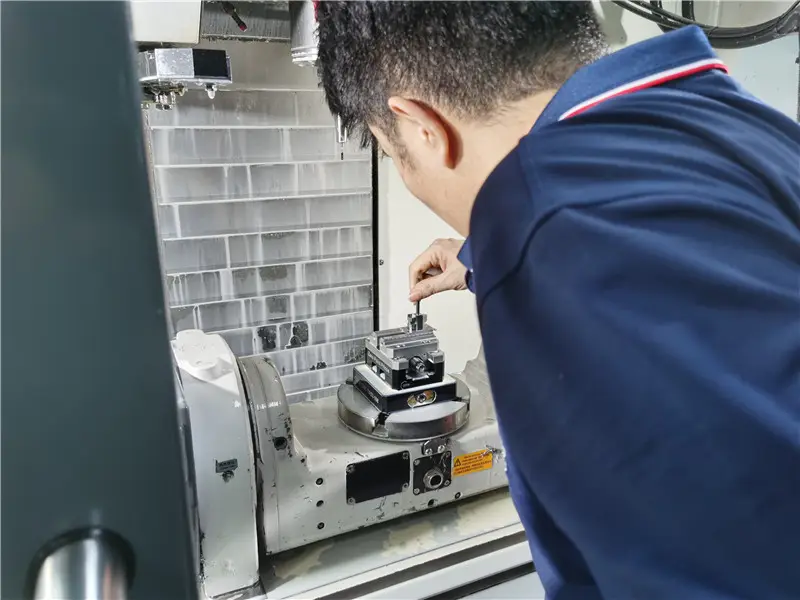
Set datums, workholding, allowances and process sequence.
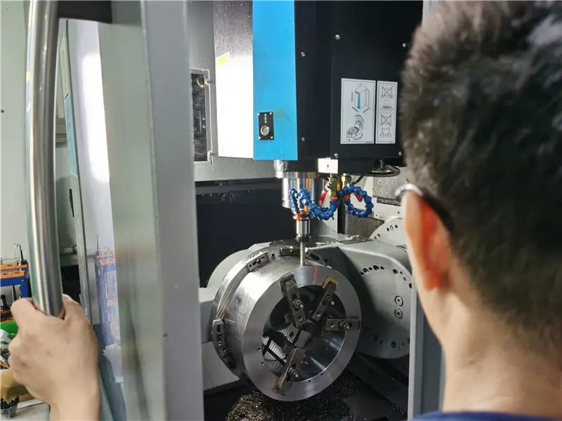
Machine blanks, bores, hubs, shafts and tooth geometry.
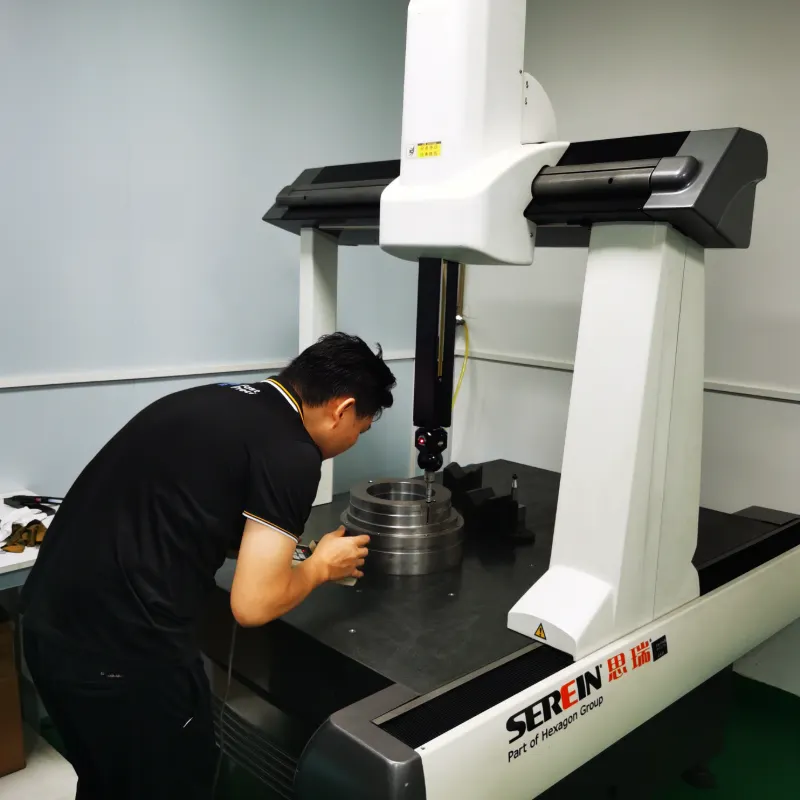
Verify specified features and protect teeth for shipment.
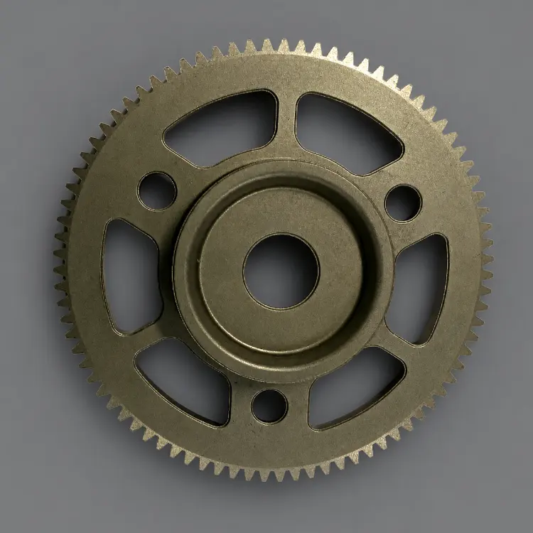
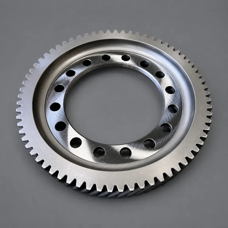
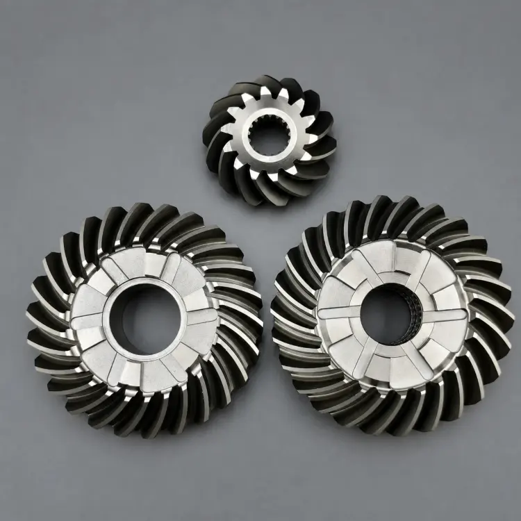
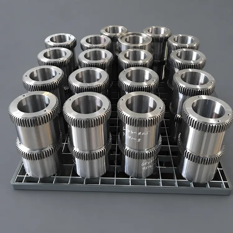
Machined Gear Projects
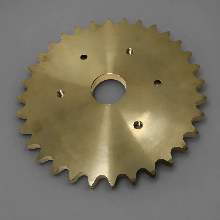
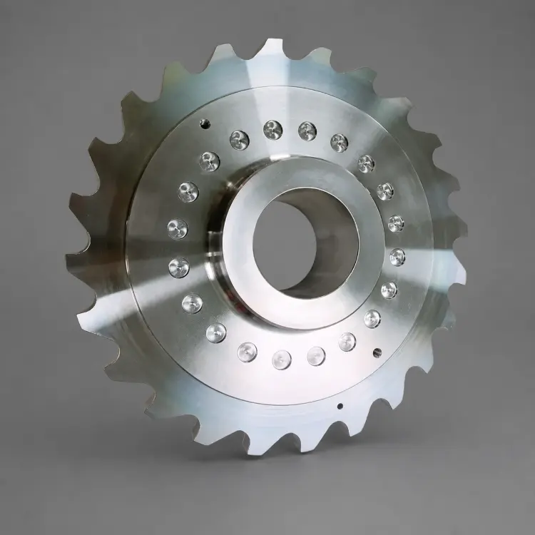
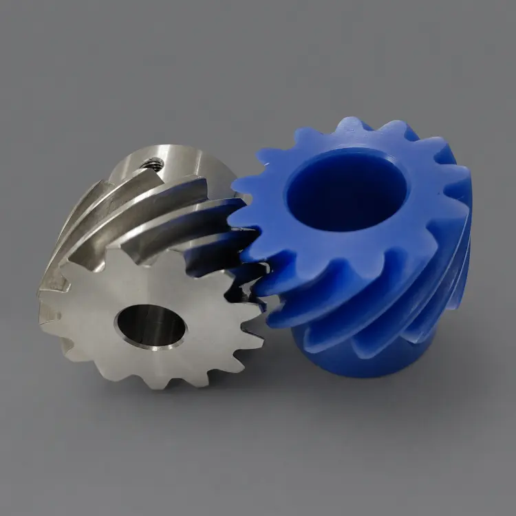
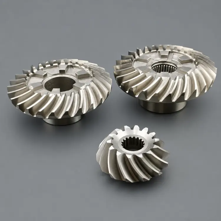
Custom CNC-Machined Gear Parts
Prototype and production gears in different structures, materials and finishes.
Quotation Preparation
Prepare a Complete Gear Drawing Package
Clear technical inputs reduce assumptions and help confirm the process, inspection scope and delivery plan.
Custom Gear FAQ