
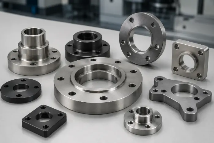
Custom Flange Component
Custom Flange Part Machining
Drawing-based CNC flange machining for piping, valves, pumps and equipment interfaces. Send the flange geometry, material, sealing face and inspection requirements for an engineering review and transparent quote.
Prototype, low-volume and repeat-production flange parts are planned from the approved drawing.
Upload Your Flange Drawing →Flange Structures
Flange Types and Design Options
Choose the connection structure first, then confirm the standard, pressure class, sealing face and service conditions.
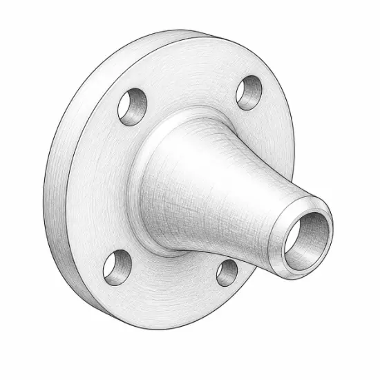
Weld Neck
Tapered neck for high-pressure, high-temperature or cyclic service.
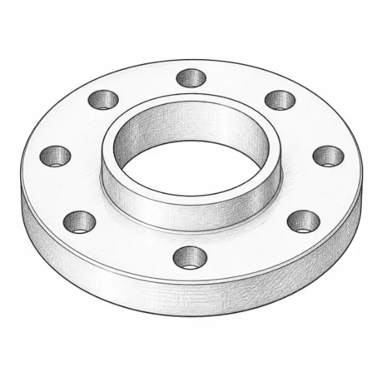
Slip-On
Practical welded connection for general piping systems.
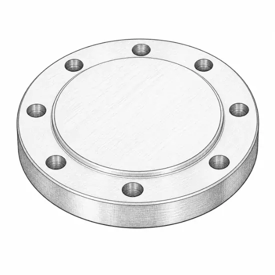
Blind
Solid closure for isolation, testing or future expansion.
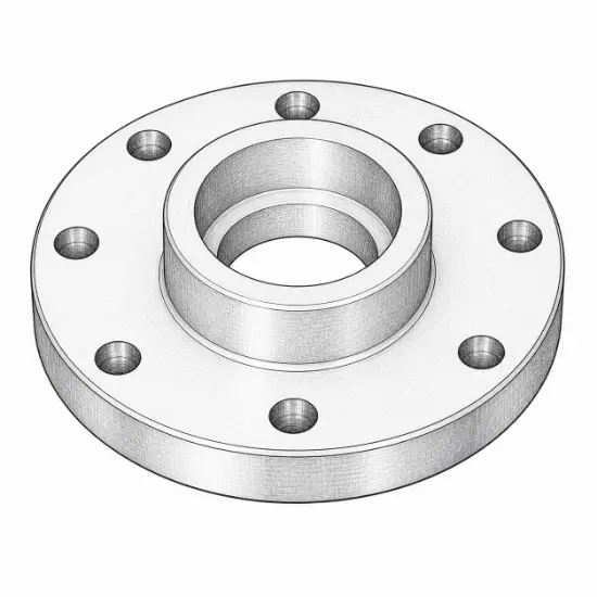
Socket Weld
Compact rigid connection for selected small-bore piping.
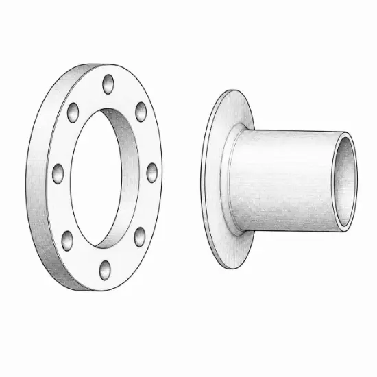
Lap Joint
Loose flange arrangement for alignment and repeated disassembly.
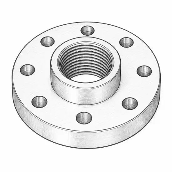
Threaded
Non-welded connection where the design and service permit threads.
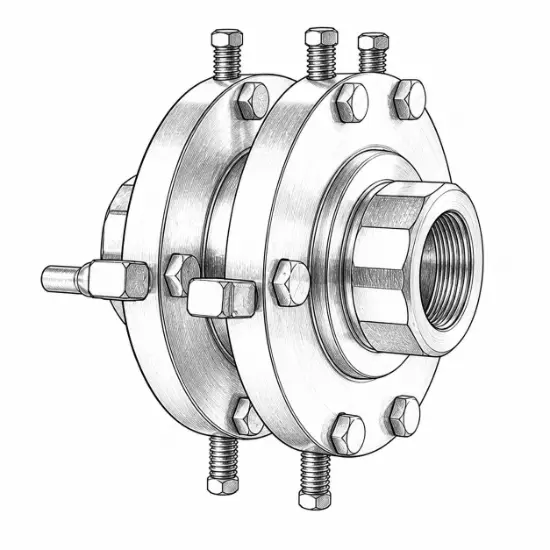
Orifice
Machined pressure taps and plate location for flow measurement.
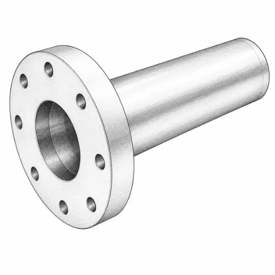
Integral
Rigid flange formed with the pipe or equipment body.
Material and Sealing Selection
Flange Materials and Sealing Faces
Compare metals and engineering plastics by grade, load, temperature, corrosion exposure, sealing face and service environment.
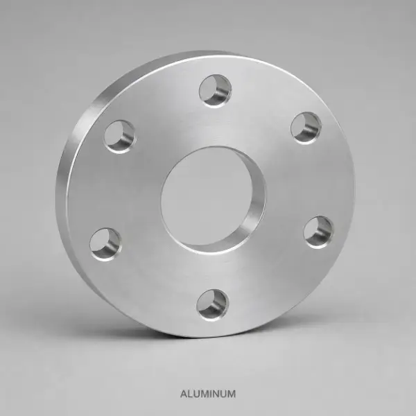
Aluminum
Lightweight, easy to machine and resistant to atmospheric corrosion.
- Common Grades
- 6061-T6, 6082-T6, 7075-T6
- Pressure & Temperature
- Low to medium pressure; typically ambient to moderate temperature.
- Sealing Faces
- FF and RF; use compatible soft or coated gaskets to protect the face.
- Typical Environment
- Lightweight equipment, ventilation and general industrial piping.
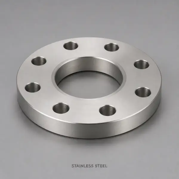
Stainless Steel
High strength, cleanability and broad corrosion resistance.
- Common Grades
- 304, 304L, 316, 316L, 321
- Pressure & Temperature
- Medium to high pressure; ambient to elevated temperature according to grade.
- Sealing Faces
- FF, RF and RTJ; face finish must match the gasket and service standard.
- Typical Environment
- Chemical, medical, food, pharmaceutical and wet-service systems.
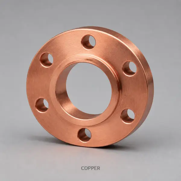
Copper
Excellent thermal and electrical conductivity with good machinability.
- Common Grades
- C101, C110, C122
- Pressure & Temperature
- Low to medium pressure; low to moderate temperature.
- Sealing Faces
- FF and RF with a gasket compatible with copper and the process fluid.
- Typical Environment
- Cooling loops, heat exchangers, electrical and temperature-control systems.

Brass
Free-cutting, wear-resistant and dimensionally stable.
- Common Grades
- C360, C464, C693
- Pressure & Temperature
- Low to medium pressure; ambient to moderate temperature.
- Sealing Faces
- FF and RF; confirm gasket and galvanic compatibility.
- Typical Environment
- Water systems, instruments, valves and non-aggressive fluids.
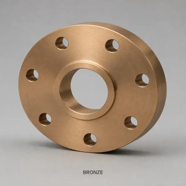
Bronze
Wear resistance, dependable sliding behavior and strong seawater performance.
- Common Grades
- C932, C954, C958
- Pressure & Temperature
- Low to medium pressure; ambient to moderate temperature.
- Sealing Faces
- FF, RF and RTJ when the alloy, gasket and service specification are compatible.
- Typical Environment
- Marine equipment, pumps, valves and water-bearing systems.
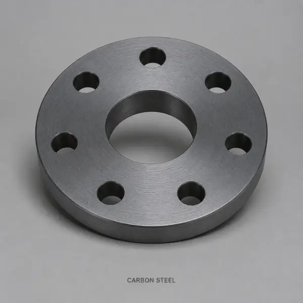
Carbon Steel
High load capacity, broad availability and cost efficiency.
- Common Grades
- A105, A350 LF2, C20, Q235
- Pressure & Temperature
- Low to high pressure depending on grade, dimensions and governing standard.
- Sealing Faces
- FF, RF and RTJ; specify suitable gasket and corrosion protection.
- Typical Environment
- Industrial piping, power equipment and structural connections.
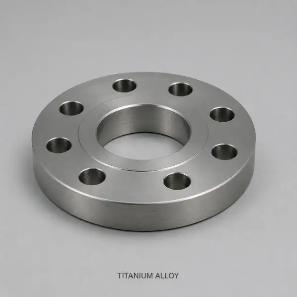
Titanium
High strength-to-weight ratio with strong resistance to chloride environments.
- Common Grades
- Grade 2, Grade 5 (Ti-6Al-4V)
- Pressure & Temperature
- Medium to high pressure; ambient to elevated temperature according to grade.
- Sealing Faces
- FF, RF and RTJ; protect the face and control galling during assembly.
- Typical Environment
- Aerospace, marine, chemical and highly corrosive service.
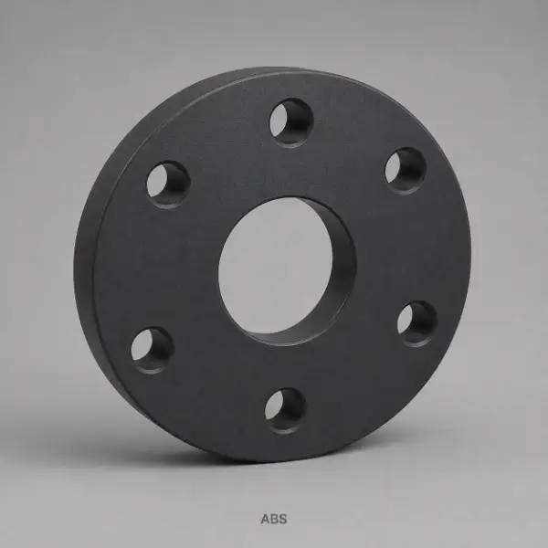
ABS
Lightweight, impact-resistant and economical for noncritical connections.
- Common Grades
- General-purpose ABS, flame-retardant ABS
- Pressure & Temperature
- Low pressure and near-ambient temperature.
- Sealing Faces
- FF and RF with soft gaskets; avoid excessive bolt preload.
- Typical Environment
- Non-aggressive media, covers and light-duty piping.
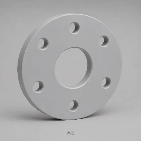
PVC
Low weight with useful resistance to moisture, acids and alkalis.
- Common Grades
- PVC-U, PVC-C
- Pressure & Temperature
- Low to medium pressure; PVC-C supports higher service temperature than PVC-U.
- Sealing Faces
- FF and RF with elastomeric gaskets and controlled bolt load.
- Typical Environment
- Water treatment, drainage and ambient chemical piping.
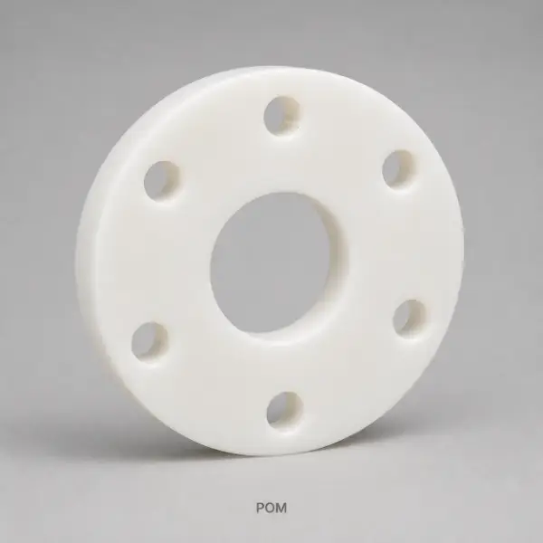
POM / Delrin
Low friction, wear resistance and good dimensional stability.
- Common Grades
- POM-C, POM-H
- Pressure & Temperature
- Low pressure; ambient to moderate temperature.
- Sealing Faces
- FF and RF with soft gaskets and even contact stress.
- Typical Environment
- Low-friction connections and assemblies requiring frequent disassembly.
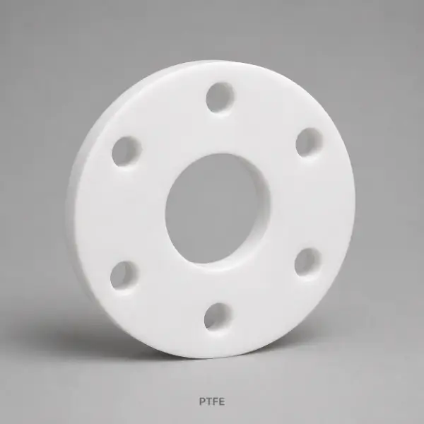
PTFE
Exceptional chemical resistance with very low friction.
- Common Grades
- Virgin PTFE, glass-filled PTFE, other filled grades
- Pressure & Temperature
- Low to medium pressure across a broad chemical-service temperature range.
- Sealing Faces
- FF, RF and lined faces with soft or PTFE-compatible gaskets.
- Typical Environment
- Strong chemicals, process piping and corrosion-resistant linings.

HDPE
Tough, moisture-resistant and suitable for many chemical-transfer systems.
- Common Grades
- HDPE, PE100
- Pressure & Temperature
- Low to medium pressure; ambient to moderate temperature.
- Sealing Faces
- FF and RF with elastomeric gaskets and allowance for creep and expansion.
- Typical Environment
- Water treatment, chemical transfer and outdoor service.
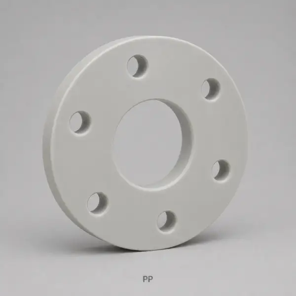
PP
Low density with useful resistance to water and many chemicals.
- Common Grades
- PP-H, PP-R, PP-C
- Pressure & Temperature
- Low to medium pressure; ambient to moderate temperature according to grade.
- Sealing Faces
- FF and RF with soft gaskets and controlled compression.
- Typical Environment
- Chemical lines, liquid transfer systems and humid environments.
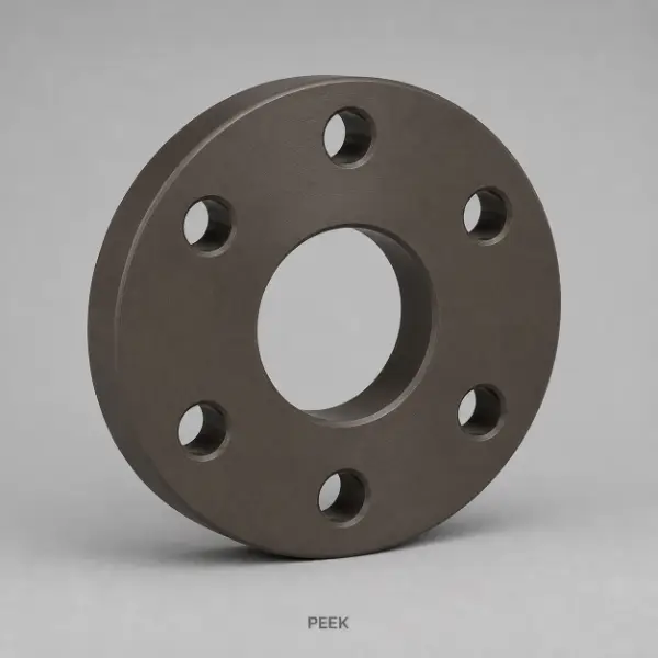
PEEK
High strength, chemical resistance and elevated-temperature capability.
- Common Grades
- Virgin PEEK, glass-filled PEEK, carbon-filled PEEK
- Pressure & Temperature
- Low to medium pressure; elevated temperature according to grade and design.
- Sealing Faces
- FF, RF and special lined faces with compatible high-performance gaskets.
- Typical Environment
- Semiconductor, medical, aerospace and demanding industrial systems.
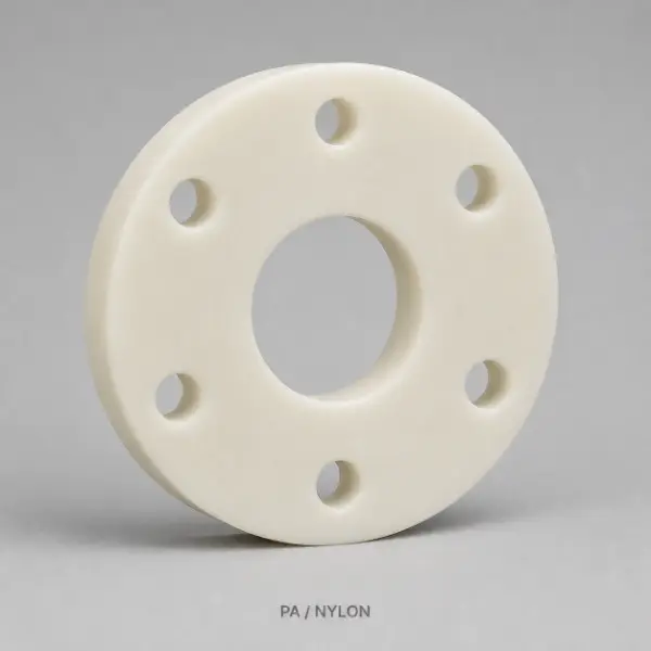
Nylon / PA
Lightweight, wear-resistant and impact tolerant.
- Common Grades
- PA6, PA66, reinforced nylon
- Pressure & Temperature
- Low pressure; ambient to moderate temperature with moisture allowance.
- Sealing Faces
- FF and RF with soft gaskets; account for moisture-driven expansion.
- Typical Environment
- Lightweight, low-pressure and general wear applications.
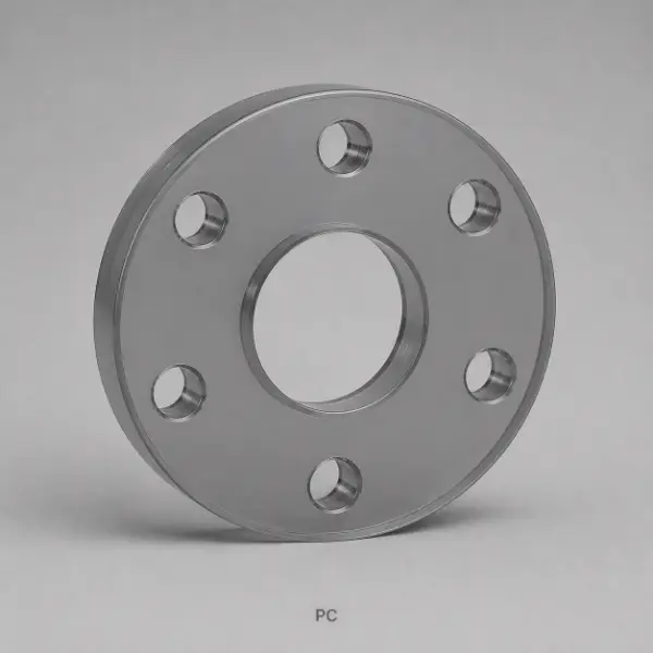
Polycarbonate / PC
High impact resistance, dimensional stability and optional transparency.
- Common Grades
- PC, flame-retardant PC, transparent PC
- Pressure & Temperature
- Low pressure; ambient to moderate temperature.
- Sealing Faces
- FF and RF with soft gaskets and low, even bolt load.
- Typical Environment
- Inspection windows, transparent covers and lightweight structures.
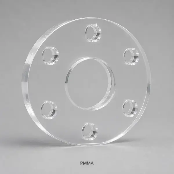
PMMA / Acrylic
Optical clarity, weatherability and a clean visual finish.
- Common Grades
- Cast PMMA, extruded PMMA
- Pressure & Temperature
- Low pressure and near-ambient temperature.
- Sealing Faces
- FF and RF with soft, nonabrasive gaskets.
- Typical Environment
- Viewing windows and non-high-pressure transparent connections.
Pressure and temperature suitability depend on material grade, flange size, wall thickness, bolts, gasket and the governing standard. Confirm the final selection against the drawing and operating conditions.
Drawing-Based Capability
CNC Flange Machining Parameters
Key production ranges are reviewed against material, geometry, clamping, sealing-face and inspection requirements.
| Capability | Metal Flanges | Engineering-Plastic Flanges |
|---|---|---|
| Typical dimensional tolerance | ±0.02 mm | ±0.05 mm |
| Outside diameter | 10–1000 mm | 10–600 mm |
| Minimum wall thickness | 1.0 mm | 1.5 mm |
| Minimum bore / hole | 2.0 mm | 2–3 mm |
| Typical machined roughness | Ra 0.8–3.2 μm | Ra 1.6–3.2 μm |
Final values depend on part size, material condition, geometry and inspection method; critical requirements must be specified on the drawing.
Manufacturing and Inspection
From Drawing Review to Final Inspection
One controlled route covers programming, machining, dimensional verification and shipment protection.
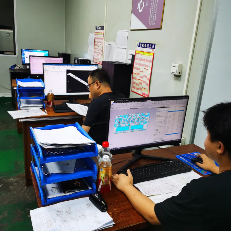
Confirm datums, standard, sealing face and critical dimensions.
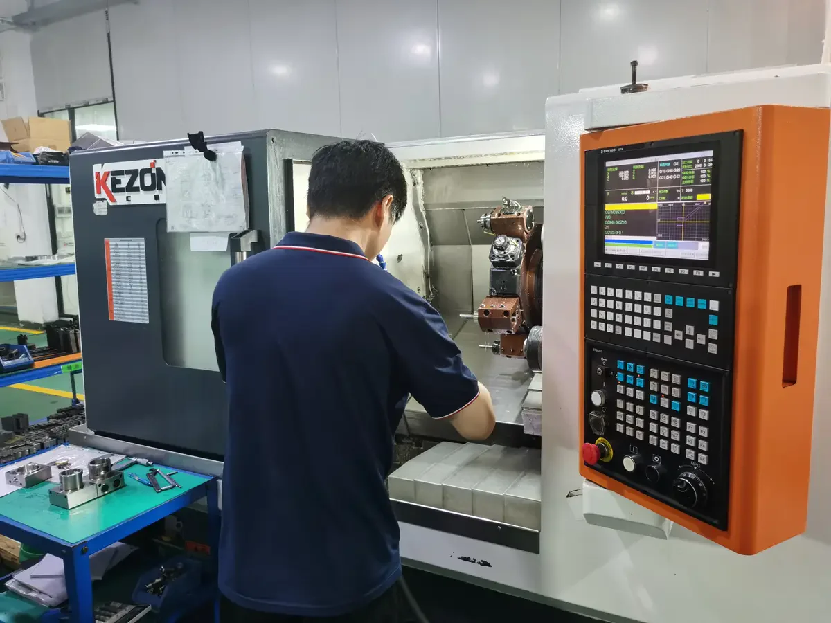
Turn, mill, drill and groove features in the approved sequence.
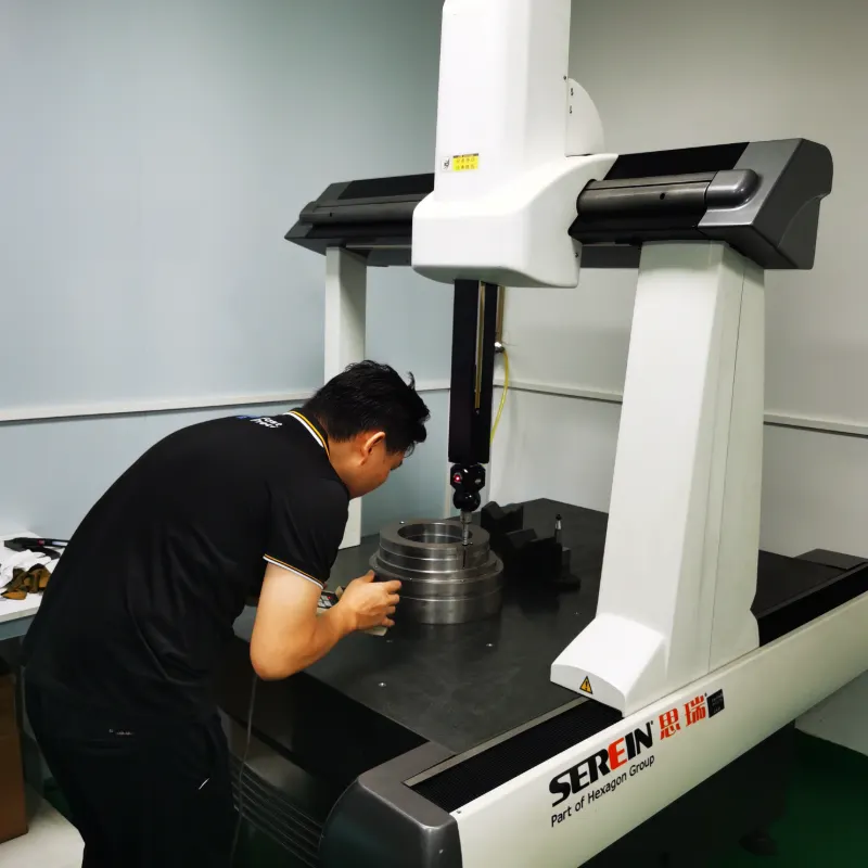
Verify bore, OD, bolt pattern, flatness and positional features.
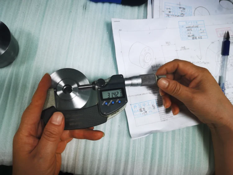
Protect sealing faces and prepare requested records for shipment.
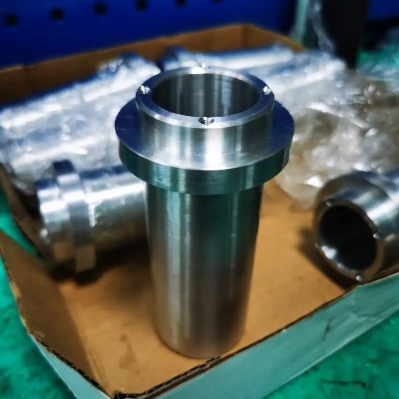
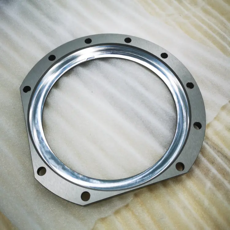
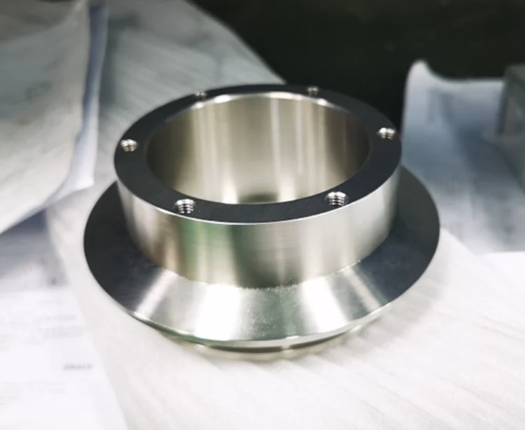
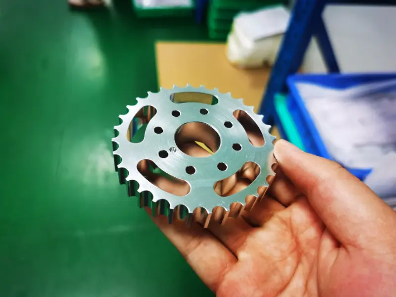
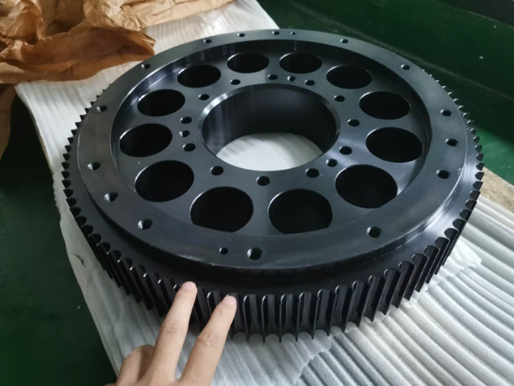
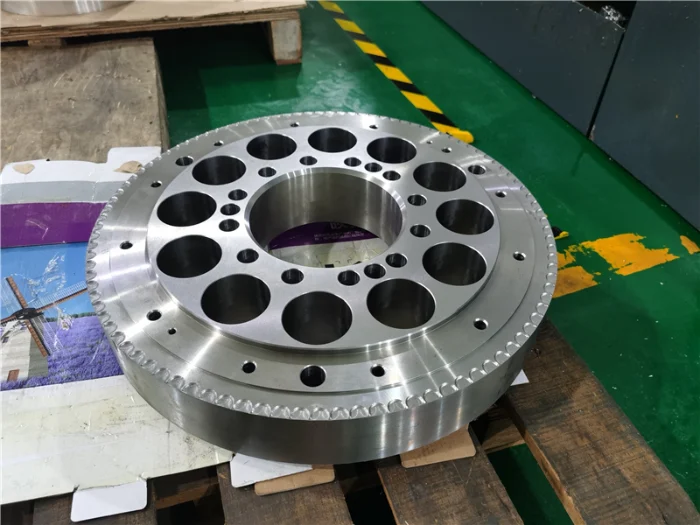
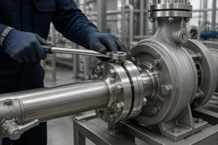
Machined Flange Projects
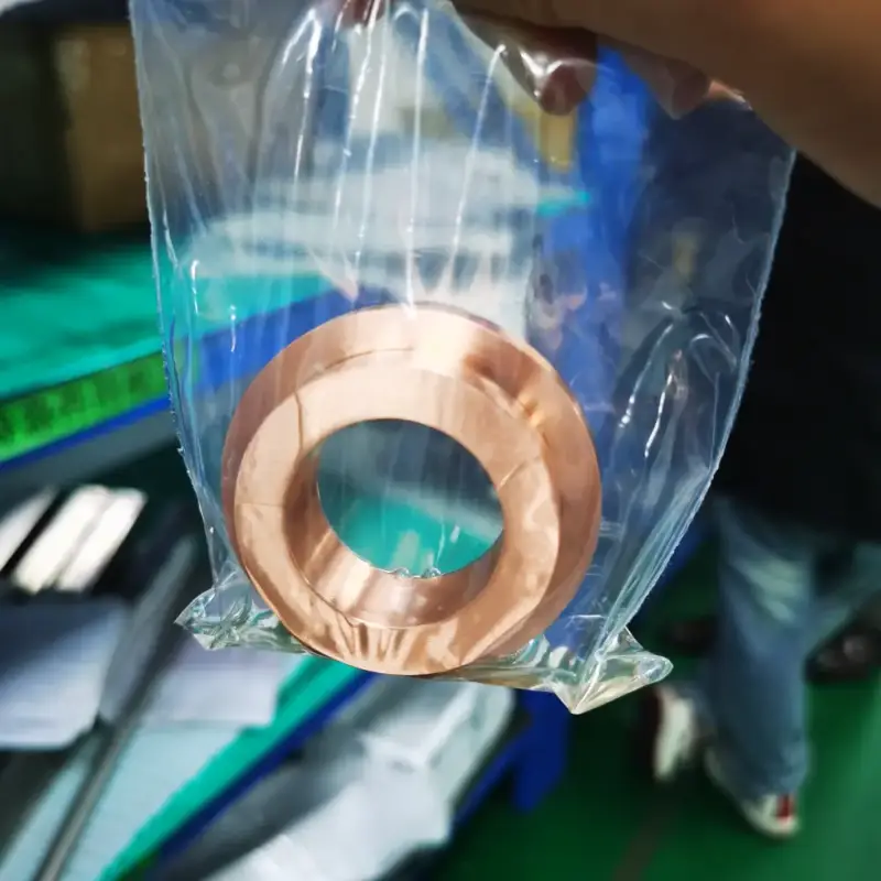
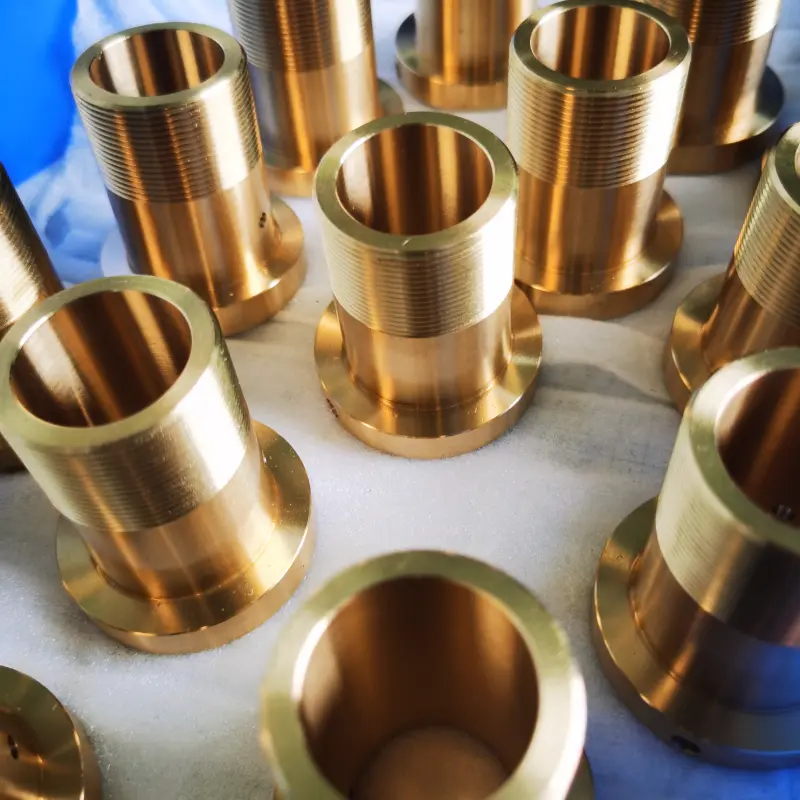
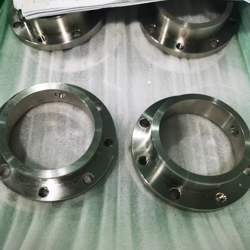
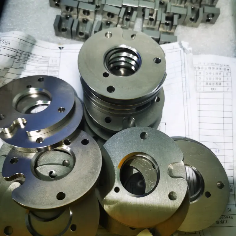
Custom CNC-Machined Flange Parts
Metal and engineering-plastic flange components produced from customer drawings.


Application Review
Specify the Flange Around Its Operating Conditions
A useful quotation starts with the interface, sealing and documentation requirements—not only the outside diameter.
- 2D drawing or 3D CAD file
- Material grade and condition
- Flange standard and pressure class
- Sealing face and gasket requirement
- Quantity and delivery target
- Inspection and documentation scope
Flange Machining FAQ