
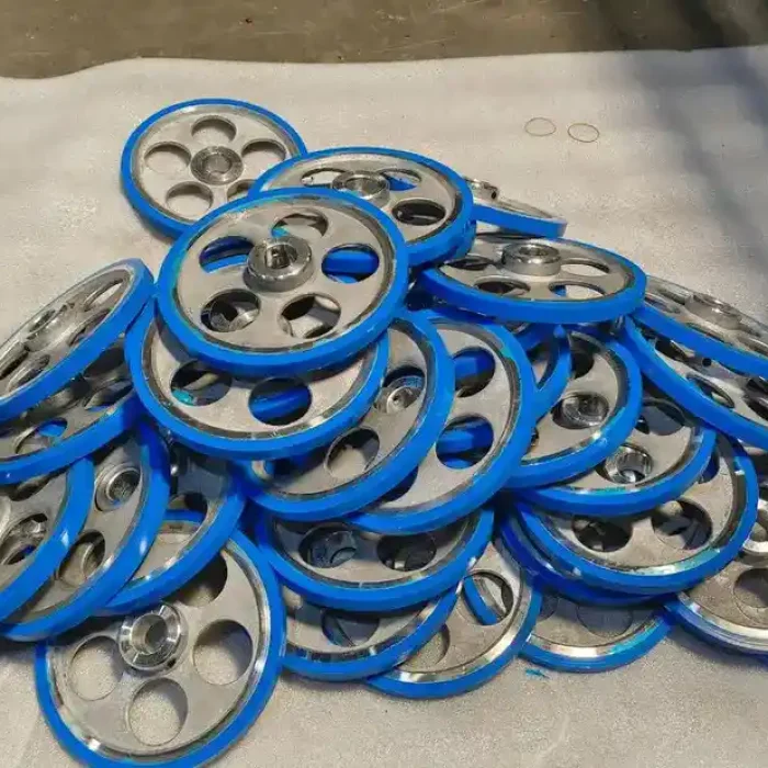
Rigid Substrate + Functional Overmold
Custom Overmolding Services
Add grip, sealing, cushioning or impact protection by molding a compatible soft layer onto a rigid plastic or metal substrate. Send your drawing for a clear tooling and production review.
Upload Your Part Drawing →Multi-Material Molding
How Overmolding Works
A prepared substrate is located in a mold before the second material is formed around selected areas.
Prepared substrate, second molding operation
A molded or machined insert is loaded into the overmold tool before injection.
Two materials in one automated mold cycle
The substrate and overmold are produced in sequence within one molding system.
Grip and Ergonomics
Create a soft, non-slip contact surface without a separate grip.
Sealing and Protection
Integrate seals, protected edges or local environmental barriers.
Impact and Vibration Control
Absorb shock, reduce noise and protect sensitive components.
Fewer Assembly Steps
Replace selected adhesive, fastener or cover operations.
Material Pairing
Typical Combinations to Evaluate
Compare common substrate and overmold families before selecting the exact supplier grades.
ABS / PC + TPE or TPU
Soft-touch housings, grips and impact zones using an adhesion grade selected for the substrate.
PP + TPE or TPV
Handles, seals and flexible interfaces using a polypropylene-bonding elastomer grade.
PA + TPE or TPU
Wear-resistant structures with soft features; moisture control and grade-specific bonding are essential.
PBT + TPE or TPC
Electrical and industrial components requiring dimensional stability and a resilient interface.
PC, PBT or PA + LSR
Sealing and high-performance interfaces after substrate heat resistance and adhesion are verified.
Metal + TPU, TPE or Silicone
Machined inserts with protective or ergonomic layers, normally supported by retention geometry or primer.
Design for Reliable Bonding
Overmolding Design Guidelines
Define retention, layer transitions, shutoffs, locating and material flow before tooling.
Mechanical Retention
Add holes, grooves, undercuts or wraparound features where chemical adhesion alone is insufficient.
Controlled Layer Thickness
Keep the overmold layer reasonably uniform and avoid abrupt sections that promote sink, voids or uneven cooling.
Protected Edges
Terminate the soft layer at a defined shoulder or recess to reduce peeling and feathered edges.
Draft and Shutoffs
Provide draft for ejection and robust shutoff faces to control flash at the material boundary.
Stable Substrate Location
Use repeatable locating and support features so injection pressure cannot shift or deform the insert.
Gate and Vent Strategy
Plan flow length, gates and end-of-fill venting to reduce trapped air, weld lines and incomplete filling.
Overmolding Capabilities
| General dimensional tolerance | About ±0.05 mm |
|---|---|
| Precision feature reference | Reviewed to ±0.02 mm |
| Maximum part envelope | 500 × 400 × 200 mm |
| Maximum metal insert weight | Up to 3 kg |
Production and Inspection
From Material Review to Delivery
A controlled route protects the substrate, bond interface and finished part.
DFM and Material Review
Confirm the substrate, overmold grade, hardness, bond method, shutoffs and critical requirements.
Tool and Insert Preparation
Build the tool, prepare the rigid substrate and protect surfaces that must remain exposed.
First-Shot Validation
Review fill, flash, appearance, dimensions, adhesion and functional performance before release.
Controlled Production
Manage drying, cleanliness, material temperatures, insert position, pressure and cooling.
Inspection and Delivery
Verify the approved criteria, trim and assemble when required, then protect parts for shipment.
Application Examples
Custom Overmolded Parts
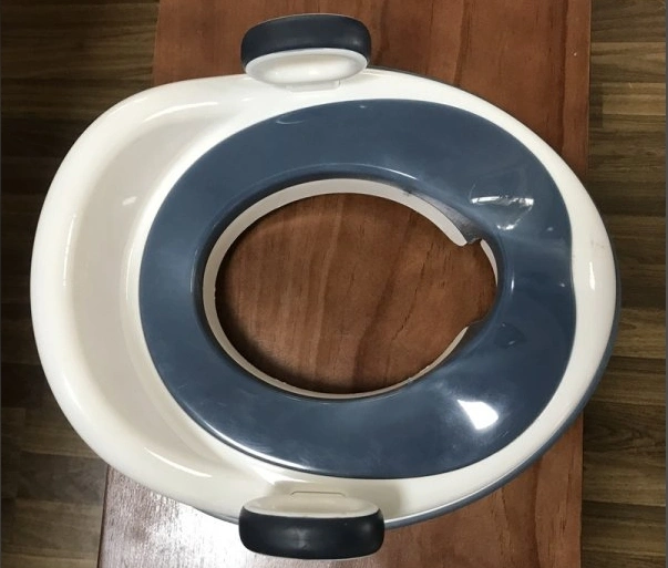
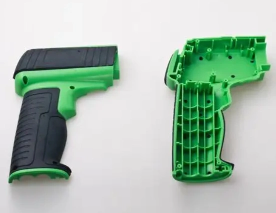
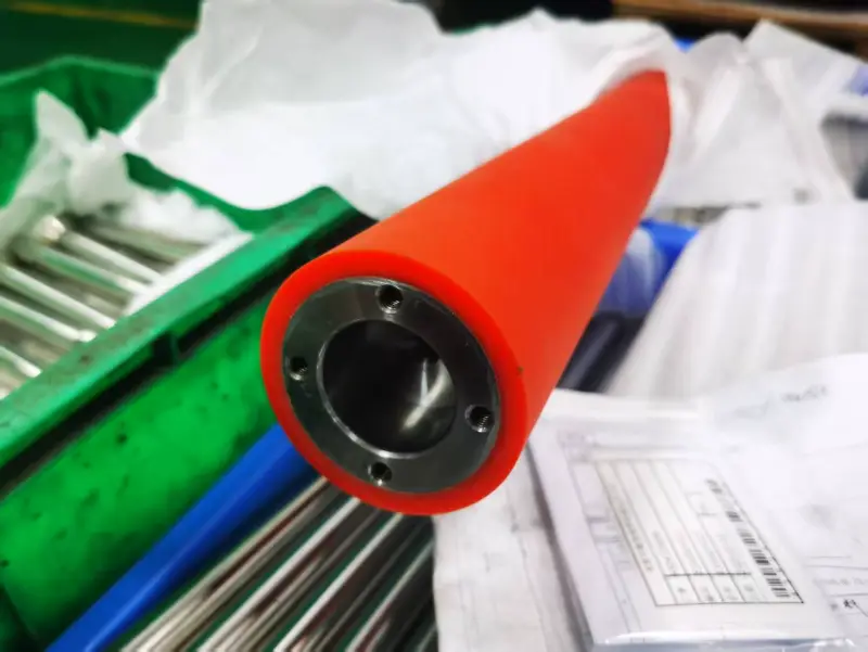
Rigid-plus-soft components for grip, sealing, protection and integrated assembly.
Overmolding FAQ
Plan Your Overmolding Project
How is overmold hardness specified?
Soft materials are commonly specified by Shore hardness. Select the value from the required grip, compression, sealing and wear performance, then confirm it against the chosen grade.
Can the overmold color and texture be customized?
Yes. Color, gloss and mold texture can be reviewed with the selected material, but appearance standards and masterbatch requirements should be defined before tooling release.
Can an existing insert be used for overmolding?
Yes, if its material, tolerances, locating features, cleanliness and temperature resistance suit the molding process. Samples may be needed for trial fitting and bond validation.
What affects overmolding tooling cost?
Part size, cavities, undercuts, side actions, shutoff complexity, insert loading, texture, tool life and validation requirements are the main cost drivers.
How are overmolded parts tested?
Typical checks include dimensions, appearance and adhesion, followed by project-specific pull, peel, leak, compression or functional tests when required.
What information is needed for a quotation?
Send 3D CAD and a 2D drawing with materials, hardness, color, quantity, critical dimensions, shutoff areas and functional test requirements.