
Precision Bar-Fed Manufacturing
Swiss CNC Machining Services
Weldo manufactures small-diameter and slender parts whose runout, feature alignment and surface quality are difficult to maintain on standard lathes. Guide-bushing support and coordinated turning, milling, drilling and backworking reduce deflection and setup-to-setup variation from prototype through repeat production.
Why Swiss Machining
Support the Part at the Cutting Point
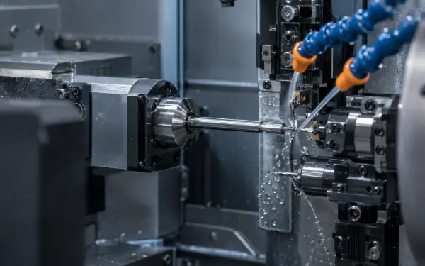
A sliding headstock feeds the bar through a guide bushing so the tool cuts next to the support point. The short unsupported length limits bending, chatter and diameter drift on slender geometry.
Controlled Slender Features
Cutting beside the guide bushing reduces the unsupported bar length, helping control deflection, taper and vibration.
Turn and Mill Together
Diameters, flats, slots, cross holes and threads remain tied to the same programmed coordinate system.
Front and Rear Completion
The sub-spindle receives the part before cutoff so rear faces, bores and chamfers can be finished without manual refixturing.
Repeatable Production
Controlled bar feeding and a stable tool sequence support consistent cycle time and inspection results across repeat orders.
Operations Combined in One Swiss Cycle
These values are quotation references, not universal limits. The approved drawing, material, bar condition, feature geometry and inspection plan define the final manufacturing capability.
Part Families
Precision Parts Built Around the Bar
The best candidates combine rotational geometry with tight feature relationships. Each part family below highlights the functional requirements that determine the machining route.
Precision Shafts & Pins
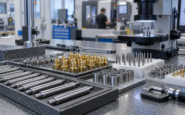
Dowel pins, valve stems, probe shafts and actuator pins are manufactured around diameter consistency, straightness, runout and controlled tip geometry.
Bushings & Sleeves
Internal and external diameters are sequenced to control wall thickness, coaxiality and end-face relationships without excessive clamping pressure.
Fittings & Connectors
Ports, sealing grooves, cross holes, flats and threads can be completed before cutoff, reducing datum changes and secondary handling.
Medical & Instrument Parts
Small threaded hardware, guides and instrument components require traceable materials, controlled burrs, clean surfaces and clearly defined inspection records.
Material Strategy
Materials and Finishing Options
At small diameters, chip shape, work hardening, thermal conductivity and material stability directly affect tool life and diameter control. Finishing allowance is included before machining begins.
Stainless Steel
Used for fittings, valve parts, medical components, fasteners and corrosion-resistant shafts. The machining plan controls work hardening, long chips, cutting heat and tool wear.
Carbon and Alloy Steel
Selected for pins, transmission shafts, gear shafts, bushings and high-strength fasteners. Heat-treatment distortion and coating buildup are included in the machining allowance and inspection plan.
Aluminum Alloys
Used for lightweight fittings, electronic connectors, sensor components and instrument parts. Sharp tools and clean handling control built-up edge and surface scratching.
Brass and Copper Alloys
Used for terminals, electrical contacts, fluid fittings and valve components. Grade selection aligns conductivity, corrosion resistance, strength, machinability and lead-content requirements.
Titanium
Applied to lightweight, corrosion-resistant and high-strength components. The machining route uses positive tool geometry, controlled cutting heat and disciplined tool-life management.
POM / Acetal
POM is used for insulating shafts, bushings, spacers, rollers and precision mechanical components. Machining controls cutting heat, deformation and clamping pressure.
PEEK
PEEK serves medical equipment, semiconductor systems and demanding industrial assemblies. Material conditioning, cutting heat, residual stress and burr formation are controlled in the process.
PTFE, Nylon and PMMA
Each plastic follows a separate process. PTFE requires deformation control, nylon requires moisture-aware inspection, and PMMA requires heat, scratch and residual-stress control.
DFM and Cost Control
Convert Critical Features into a Stable Process
DFM review connects each functional requirement to the bar condition, tool access, machining sequence and measurement method needed to hold it in production.
Length-to-Diameter Ratio
Bar straightness, roundness and guide-bushing clearance are treated as process inputs. An unsuitable bar can create taper or runout even when the machine motion is accurate.
Thin Walls
Cutting order, tool sharpness and sub-spindle grip force are balanced to prevent elastic collapse during machining and springback after release.
Small and Deep Holes
Hole depth is reviewed against drill diameter, coolant delivery and chip evacuation. Inspection access is defined before a deep-hole tolerance is accepted.
Cross-Hole Intersections
Breakthrough location and edge requirements determine tool direction and deburring method. Internal burr acceptance must be measurable rather than described only as “burr-free.”
Threads and Runout
Thread standard, class, engagement length, relief and gauge method are linked to the datum diameter controlling assembly runout.
Tolerance Allocation
Tight tolerances are reserved for fits, sealing diameters and locating relationships. Nonfunctional dimensions use an economical general tolerance.
Primary Cost Drivers
Production Control
Quality from First Article to Final Shipment
Quality control begins with feature-specific measurement planning. First-article results establish offsets and inspection frequency; in-process trends identify tool wear before a critical dimension leaves tolerance.
Inspection Scope
- Material grade and bar condition
- OD, ID and shoulder locations
- Roundness and coaxiality
- Hole diameter and position
- Thread gauge inspection
- Surface roughness
- Cross-hole burrs
- Coating and heat-treatment results
Available Documentation
State document requirements during quotation so traceability is built into the production plan.
Application Support
Swiss Machining for Critical Industries
Part geometry, material condition, surface requirements and inspection depth are aligned to the actual service environment.
Instrument shafts, holders, guides, threaded components and precision hardware.
Valve components, sensor housings, pins, connectors, bushings and drive parts.
Conductive pins, terminals, contacts, miniature housings and connectors.
Nozzles, valve stems, fittings, adapters, sealing grooves and internal passages.
Locating pins, guide shafts, actuator components, spacers and bushings.
Adjustment components, lightweight sleeves, shafts and precision fasteners.
Why Weldo
One Factory, One Controlled Route
Weldo coordinates drawing review, material preparation, machining, deburring, finishing, inspection and shipment through one workflow.
- Prototype and repeat production
- Engineering and tolerance review
- Swiss turning and live-tool operations
- Material and finishing coordination
- First-article and in-process inspection
- Production traceability
- Quality-document support
- International order coordination
Buyer Questions
Swiss CNC Machining FAQs
A Swiss machine is a sliding-headstock lathe designed for bar-fed parts. In guide-bushing mode, the bar moves through a bushing while tools work close to the support point, limiting deflection in slender parts. Modern machines also add driven tools and sub-spindles for milled, drilled, threaded and rear-side features.
An automatic feeder supplies bar stock to the main-spindle collet. The sliding headstock moves the bar through the guide bushing while gang-mounted tools cut near the support point. Driven tools add off-axis features, and the sub-spindle receives the part before cutoff to complete rear operations.
Choose it when a part combines a small diameter, slender geometry, multiple features and repeat quantities. Close support controls deflection, while automatic feeding and integrated operations reduce handling. For the right component, that produces stable feature relationships with fewer setups.
The name comes from Switzerland's watchmaking industry, where sliding-headstock automatic lathes were developed for small precision components. Today, “Swiss” describes the machine architecture rather than the country where the machine or part is manufactured.
A conventional lathe holds the workpiece mainly in a chuck or collet and moves tools along the exposed stock. A Swiss lathe moves the bar through a guide bushing and supports it near the cut. Swiss architecture suits slender, small-diameter parts; conventional lathes remain more economical for short, rigid and larger-diameter components.
Yes. Swiss machining is practical for prototypes that need guide-bushing support, driven-tool features or a route intended for later production. A simple one-off part may cost less on a conventional lathe, but using the Swiss route early validates the tooling, datums and cycle planned for repeat orders.
There is no single tolerance for every Swiss-machined part. Diameter, unsupported length, bar quality, material, feature geometry, thermal stability and inspection method affect the result. Weldo confirms critical tolerances after drawing review and verifies them through first-article inspection.
Cross-hole burr control starts with tool direction, edge-break geometry and stable tool condition. Accessible edges are chamfered or mechanically deburred; internal intersections receive an application-specific process. Inspection confirms that loose burrs cannot obstruct flow, interfere with assembly or damage a mating component.