
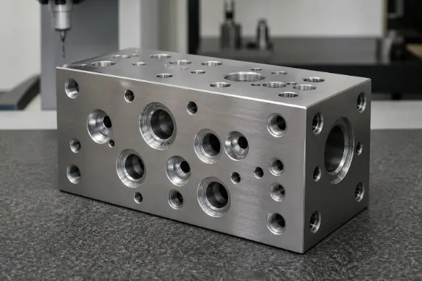
A hydraulic manifold block connects pumps, control valves, actuators, and return lines through internal passages. It directs, distributes, and regulates hydraulic fluid within an integrated hydraulic circuit.
Compared with conventional external piping, a manifold block provides a more compact layout. It also reduces the number of fittings and potential leakage points. However, deep holes, intersecting passages, cartridge valve cavities, port threads, and precision sealing faces make these components difficult to manufacture.
Hydraulic Manifold Block CNC Machining normally includes six-face milling, deep-hole drilling, valve-cavity machining, port machining, and sealing-face finishing. Reliable production also requires suitable CNC machining capabilities, followed by internal deburring, cleaning, surface treatment, and pressure testing.
The quality of a manifold block cannot be judged by appearance alone. Passage deviation, internal burrs, cross-circuit leakage, and residual chips can increase pressure loss, cause leakage, or make hydraulic valves stick. The following sections explain ten common machining problems and their practical solutions.
1. What Should Be Done When the Material or Blank Does Not Meet Machining Requirements?
Material quality directly affects the strength, pressure capacity, and machining stability of a manifold block. Common problems include an incorrect material grade, an incorrect delivery condition, insufficient machining allowance, and missing material certificates.
The blank may also contain internal cracks, inclusions, porosity, or voids. These defects may not be visible during a surface inspection, but they can compromise pressure integrity.
Before CNC machining, verify the material grade, heat or batch number, and delivery condition. The material certificate, blank dimensions, and machining allowance must also conform to the drawing and purchase order.
Critical pressure-bearing blanks should undergo nondestructive testing as specified by the drawing or quality plan. Ultrasonic testing is mainly used to identify internal discontinuities. Magnetic particle testing is suitable for surface and near-surface cracks in ferromagnetic materials. Liquid penetrant testing can detect surface-breaking defects in nonporous materials.
Qualified forgings generally have a dense structure and are suitable for high-pressure and cyclic loading. However, forged material is not guaranteed to be completely free of internal defects. Specified material inspections are still required for critical pressure-bearing parts.
Centrifugally cast stock generally has a dense structure. Inclusions and porosity tend to concentrate near the bore or within the machining allowance, making this material suitable for hollow parts such as sleeves and rings. Pressure-bearing components still require material certification and the necessary nondestructive testing. Centrifugal casting does not guarantee a defect-free internal structure.
Large steel parts, cast-iron parts, and distortion-sensitive blanks may contain high residual stresses. These blanks should be stress-relieved or aged as specified. For aluminum manifold blocks, the material temper must be confirmed to ensure that strength and dimensional stability requirements are met.
2. What Should Be Done When Geometric Accuracy Is Out of Tolerance After Six-Face Milling?
Hydraulic manifold blocks are normally machined from several directions. Their six external faces define the overall dimensions and serve as locating datums for oil passages, valve cavities, and mounting faces.
If the blank allowance is uneven, the first datum face may be unstable. Repeated setups also introduce datum-transfer errors, which can eventually cause parallelism, perpendicularity, and hole-position tolerances to be exceeded.
A sound CNC machining sequence begins with rough milling all six faces and then establishing a common datum system. Semi-finishing and finishing follow. Sufficient stock must remain after roughing; the part should not be machined directly to its final dimensions during this stage.
Sealing faces, valve mounting faces, and critical hole patterns should use common datums wherever possible. Four-axis or five-axis CNC machining can reduce the number of setups and help maintain the positional relationships among features on different faces.
Milling can meet the face-machining requirements of most manifold blocks. If the drawing specifies tighter flatness or surface-roughness requirements, surface grinding can be added.
For some small and medium-sized manifold blocks, a reference flatness of 0.01–0.03 mm per 100 mm may be used for sealing faces. This is not a universal acceptance standard. The final requirement must follow the drawing and the sealing design.
3. Why Does a Manifold Block Distort After CNC Machining?
Machining distortion mainly results from residual stress in the blank and uneven material removal. Clamping force, cutting heat, and the machining sequence also affect the final dimensions.
Deep holes, cavities, and weight-reduction features alter the original stress balance of the blank. After the part is released from the fixture, warping, hole displacement, or changes in the sealing faces may occur.
Parts with a high risk of distortion should be machined in stages. Complete rough machining first, perform the specified stress-relief treatment, then re-establish the datums and finish the part.
Machining stock should be removed as symmetrically as possible. The fixture must provide stable support without causing noticeable elastic deformation in thin-wall areas.
Cutting parameters and tool condition must also be controlled during CNC finishing. Excessive cutting temperature can affect hole size, flatness, and surface quality.
Heat treatment, anodizing, and electroplating may also cause dimensional changes. Masking areas, processing allowances, or post-treatment finishing plans for valve cavities, precision bores, threads, and sealing faces should be defined in advance.
4. What Should Be Done When a Deep Hole Deviates or Has a Rough Internal Surface?
Internal passages in hydraulic manifold blocks are mainly produced by CNC drilling and deep-hole machining. As hole depth increases, tool rigidity decreases, and cooling and chip evacuation become more difficult.
Common defects include axis deviation, diameter variation, taper, chatter marks, and chip blockage. A deviated passage may fail to intersect another passage at the designed location.
The material, hole diameter, hole depth, and depth-to-diameter ratio should be evaluated before machining. When conventional drilling cannot provide stable results, gun drilling, dedicated deep-hole drills, or through-coolant tools can be used.
The CNC program must use suitable spindle speed, feed rate, and peck cycles for chip evacuation. Entry guidance and spindle runout must also be controlled. Coolant must reach the cutting zone consistently.
A depth-to-diameter ratio of 5:1–20:1 can be used as a reference for process review of hydraulic manifold passages. Near the upper end of this range, dedicated deep-hole equipment, tooling, and inspection methods are generally required. This range must not be treated as a fixed capability for every hole diameter and material.
After deep-hole machining, inspect the diameter, depth, and passage continuity. Hidden areas can be examined with an industrial borescope. A CMM can only measure features accessible to its probe and cannot replace internal-passage inspection.
5. What Should Be Done When Intersecting Holes Do Not Connect at the Correct Location?
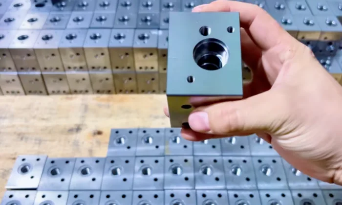
Intersecting holes connect internal passages running in different directions. The machining priorities include not only hole position but also drilling depth, intersection location, and remaining wall thickness.
Incorrect hole coordinates, tool deviation, or an incorrect programmed depth can prevent passages from connecting. Excessive drilling depth may break into an adjacent circuit and cause internal cross-port leakage.
All drilling paths should be checked against the 3D model before programming. The entry direction, machining depth, intersection point, and process-plug location must be clearly defined.
The minimum remaining wall thickness between passages must also be checked. This requirement should be determined from the material condition, working pressure, peak pressure, and cyclic loading. Insufficient wall thickness reduces pressure capacity and increases the risk of fatigue cracking.
Multi-axis CNC machining can complete hole patterns in different directions with fewer setups. This helps reduce datum-transfer errors, although tool length, rigidity, and inspection access still require review.
After machining, connected circuits and isolated circuits should be verified separately. Hole positional tolerance and coaxiality can be reviewed against a project reference of 0.02–0.05 mm. The actual tolerance depends on the hole diameter, depth, and passage structure.
Wire EDM is suitable for through-profiles, narrow slots, and certain irregular features in electrically conductive materials. It cannot replace conventional drilling for enclosed internal passages.
6. What Should Be Done When Cartridge Valve Cavities and Precision Bores Are Out of Tolerance?
A cartridge valve cavity normally contains stepped bores, guide bores, threads, and sealing features. Any local dimensional error can affect valve installation, operation, and sealing performance.
Common problems include an out-of-tolerance bore diameter, incorrect step depth, and insufficient coaxiality. An incorrect sealing-cone angle can also cause leakage. Tool wear can gradually shift dimensions during batch production.
The cartridge valve model and cavity specification must be confirmed before machining. The internal profile cannot be inferred from the external thread size alone. Different brands and product series may use different cavity geometries.
Valve cavities are normally machined with dedicated form tools or by CNC boring. Precision guide bores can be bored, reamed, or honed. The process depends on the bore diameter, coaxiality, and surface requirements.
Tool-life management should be established during production. Bore diameter, depth, sealing location, and threads must be inspected during first-article and batch production. When necessary, use a dedicated cavity gauge or the actual valve for assembly verification.
For some precision bores and sealing faces, Ra 0.4–1.6 μm can be used as a reference range during process review. The final value must comply with the valve specification and customer drawing.
7. Why Do Port Threads and Sealing Faces Leak?
Hydraulic ports provide both connection and sealing functions. An incorrect thread specification, insufficient effective depth, or damage to the sealing face can cause leakage.
BSPP, NPT, SAE straight-thread O-ring ports, and metric ports use different sealing structures. They cannot be interchanged based only on nominal diameter.
NPT ports primarily seal through tapered-thread interference and the specified thread sealant. SAE straight-thread O-ring ports seal with an O-ring. BSPP ports may use a bonded seal, O-ring, or face seal, depending on the port design.
Port threads can be produced by CNC tapping or thread milling. Thread milling is suitable for larger sizes, high-value parts, and applications that require precise control of thread depth.
The tap-drill size, pitch, and effective thread depth must be controlled. The entry chamfer and thread perpendicularity must also meet the drawing. The completed thread should be inspected with the matching thread gauge.
O-ring grooves require control of groove width, depth, and corner radii. The groove opening must be free of sharp edges and burrs that could damage the seal.
Sealing faces must be free of pronounced tool marks, impact damage, and localized depressions. Masking areas should also be defined before surface treatment. Coating buildup can alter thread fit, valve-cavity dimensions, and sealing conditions.
8. How Are Burrs Removed from Internal Intersecting Holes?
When a drill breaks into another passage, burrs readily form along the intersection edge. These burrs are usually inside the manifold block and are difficult to reach with conventional tools.
Detached burrs can contaminate the hydraulic fluid, block metering orifices, or scratch sealing faces. In severe cases, they can cause proportional or servo valves to stick.
At accessible locations, a CNC back-chamfer tool or a dedicated cross-hole deburring tool should be used first. Mechanical deburring provides better control over the location and amount of material removed.
Abrasive flow machining can be used for complex intersecting holes. The process uses an abrasive-laden medium to finish internal edges and is suitable for passages that cutting tools cannot directly reach.
Abrasive flow machining is not mandatory for every manifold block. Before use, the hole diameter, target edge radius, and permitted material removal must be evaluated. Small metering holes and restrictor orifices must be protected against unintended enlargement.
All residual abrasive must be removed after treatment. The deburred intersections should be examined with an industrial borescope. Critical circuits also require directed flushing and continuity verification.
9. Why Do Chips Remain After Cleaning?
A clean external appearance does not mean that the inside of a manifold block meets the specified cleanliness level. Small particles can remain in blind holes, thread roots, deep-hole ends, and intersecting passages.
Contaminants may include CNC chips, deburring abrasive, cleaning agents, and surface-treatment residue. Compressed-air blowing alone generally cannot remove these contaminants consistently.
The cleaning process should be developed around the passage geometry. Common methods include directed pressure flushing, filtered-fluid circulation, and ultrasonic cleaning. Ultrasonic cleaning can be used as a supplementary process, but it cannot replace directed flushing of deep holes.
Complex manifold blocks should be cleaned circuit by circuit. Reversing the flushing direction helps release particles trapped in hidden areas. After cleaning, use clean compressed air or the specified drying method.
Cleanliness cannot be assessed by visual inspection alone. When the customer has defined requirements, particle size, particle count, or residual contaminant mass should be measured.
After the cleanliness requirement has been met, all ports should be sealed immediately. Sealing faces and precision threads must also be protected separately to prevent secondary contamination during storage and transportation.
10. What Should Be Done When a Proof-Pressure or Leakage Test Fails?
A hydraulic manifold block may leak externally or between internal circuits. Internal cross-port leakage is generally more difficult to locate.
Common causes include unintended passage intersection, insufficient remaining wall thickness, and process-plug failure. Damaged threads, defective sealing faces, and material cracks can also cause leakage.
Before testing, verify the hydraulic schematic, process-plug locations, and test ports. The circuit-isolation method and test medium must also be confirmed in advance.
A proof-pressure test and a leakage test have different purposes. A proof-pressure test verifies structural integrity. A leakage test checks sealing condition and circuit isolation.
Test pressure, pressurization rate, and hold time must comply with the approved test specification. The allowable leakage rate must also be defined in advance. One general parameter cannot replace the requirements of every project.
When an abnormal result is found, first distinguish external leakage from internal cross-port leakage. Then inspect the ports, process plugs, sealing faces, and isolated circuits.
Only defects approved through an engineering review may be repaired. Cracks, unintended circuit intersections, and insufficient remaining wall thickness normally require rejection. Weld repairs must receive formal approval and use qualified welding and revalidation procedures.
How Can Stable CNC Machining of Hydraulic Manifold Blocks Be Achieved?
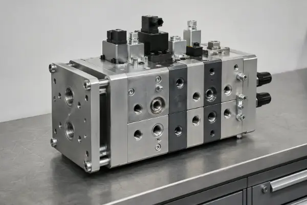
Stable production of hydraulic manifold blocks requires a complete manufacturing and verification process. The material, internal passages, and valve interfaces must be confirmed during the DFM stage rather than relying only on final inspection to identify problems.
A common datum system must be established during CNC machining. Six-face milling, deep-hole drilling, valve-cavity boring, and port-thread machining should maintain consistent positional relationships.
After machining, internal deburring, cleaning, and port capping must be completed. Final inspection should cover dimensions, passage continuity, circuit isolation, and component cleanliness.
Pressure-bearing parts should undergo proof-pressure and leakage testing according to an approved plan. The test conditions must correspond to the actual operating conditions and customer acceptance requirements.
For quotation, it is advisable to provide 2D drawings, 3D models, and the hydraulic schematic. The valve models, working pressure, peak pressure, flow rate, and fluid should also be specified. Material, quantity, surface treatment, and inspection standards are equally important.
Complete engineering information makes it possible to identify manufacturing risks early. It also reduces design changes and machining rework while improving the reliability of the hydraulic system.