Custom Power Transmission Components

Custom Timing Pulleys

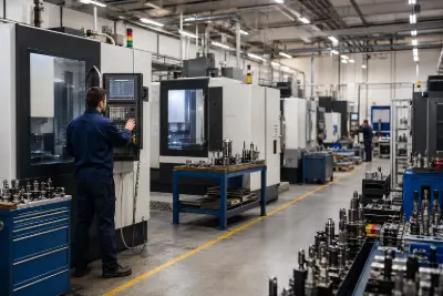
Weldo manufactures metal and engineering plastic timing belt pulleys to customer drawings. CNC turning, milling, turn-mill machining, tooth cutting, wire EDM and finishing are coordinated from one source.

Before production, we verify the tooth profile, pitch, tooth count, bore, keyway, hub geometry and assembly datum. This review protects belt compatibility and transmission accuracy.

Request Advice & Quote
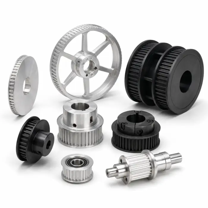
Custom CNC-machined timing belt pulley
Product Overview

What Is a Timing Pulley?

A timing belt pulley transfers rotary motion through teeth that engage with a matching synchronous belt. Positive engagement prevents normal operating slip and maintains a defined relationship between the driving and driven shafts.

Pulley performance depends on more than pitch and tooth count. The tooth form, pitch diameter, bore position, runout, flange geometry and hub connection must work as one system. An incorrect tooth profile can damage the belt even when its nominal pitch is correct.

Pulley Configurations

Timing Belt Pulley Types We Manufacture

Pulley geometry is selected around shaft connection, transmitted torque, belt tracking and available installation space.

Drive Timing Pulleys

Mounted on the motor or drive shaft to transmit torque to the belt.

  • T2.5–T10 and HTD 3M–14M
  • Keyed, clamped or set-screw hubs
  • Steel, aluminum or stainless steel

Driven Timing Pulleys

Installed on the output shaft to define transmission ratio and speed.

  • Custom tooth counts and ratios
  • Solid, webbed or lightweight bodies
  • Machined assembly datums

Toothed Idler Pulleys

Support the toothed belt side and control routing and wrap angle.

  • Profile matched to the belt
  • Bearing- or shaft-mounted designs
  • Runout controlled after assembly

Smooth Idler & Tensioner Pulleys

Contact the belt backing to control routing and operating tension.

  • Smooth or crowned surfaces
  • Integrated bearing seats
  • Controlled edge radii

Flanged Timing Pulleys

Use one or two flanges to maintain belt tracking.

  • Single- or double-flange designs
  • Pressed, bonded or integral flanges
  • Clearance matched to belt width

Clamp-Hub Timing Pulleys

Secure the pulley without damaging the shaft surface.

  • Split-clamp and taper-lock hubs
  • Low-backlash connection
  • Custom bolt patterns

Double-Sided Timing Pulleys

Engage with double-sided belts in multi-shaft motion systems.

  • Matched double-sided profiles
  • Multi-shaft motion control
  • Controlled phase relationships

Compound & Stepped Pulleys

Combine multiple belt tracks or diameters into one component.

  • Multiple pitches after review
  • Common concentric datum
  • Reduced assembly stack-up
Tooth Profile Compatibility

Timing Belt Tooth Profiles

The pulley tooth form must match the belt manufacturer’s profile. Matching pitch alone does not confirm belt compatibility.

Metric Trapezoidal T2.5, T5 and T10 for positioning equipment and general automation.
Reinforced Trapezoidal AT5, AT10 and AT20 for linear drives and higher tooth loading.
HTD Curvilinear 3M, 5M, 8M and 14M for industrial power transmission.
Imperial Trapezoidal MXL, XL, L, H and XH for imperial equipment and replacements.
Materials, Heat Treatment & Finishing

Select the Material for Your Timing Pulley

Material selection affects pulley weight, torque capacity, wear, corrosion resistance and dimensional stability. The material condition, heat treatment and surface finish must be defined before production.
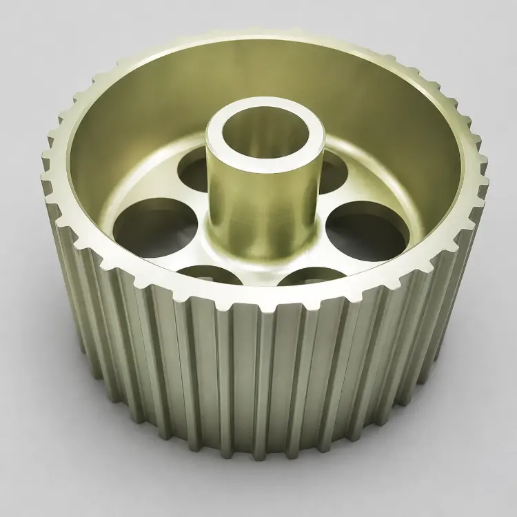
Hard-anodized custom timing belt pulley part

Aluminum Alloys

Common grades: 6061-T6, 6082-T6, 7075-T651

Aluminum reduces rotating mass and machines efficiently. 6061 and 6082 suit general automation. 7075 supports higher hub loads and compact pulley designs.

Heat Treatment

T6 and T651 are supplied heat-treated. T651 provides better machining stability. 7075-T73 or T7351 improves stress-corrosion resistance.

Surface Treatment

Clear anodizing, colored anodizing, hard anodizing, conversion coating and electroless nickel are available.

Carbon & Alloy Steels

Common grades: 1045, C45, 4140, 42CrMo4

Steel provides high stiffness, wear resistance and torque capacity. 1045 offers economical performance. 4140 provides higher fatigue strength and toughness.

Heat Treatment

Normalizing, quenching and tempering establish core properties. Induction hardening or nitriding improves selected wear surfaces.

Surface Treatment

Black oxide, phosphate coating, zinc plating and electroless nickel provide corrosion protection.

Stainless Steels

Common grades: 303, 304, 316, 17-4PH

Stainless steel supports humid, exposed and washdown environments. 303 prioritizes machinability, 316 improves corrosion resistance and 17-4PH provides higher strength.

Heat Treatment

303, 304 and 316 are normally used in a solution-annealed condition. 17-4PH uses H900–H1150 precipitation-aging conditions.

Surface Treatment

Passivation, electropolishing and bead blasting improve surface cleanliness, appearance and corrosion resistance.

Metal pulley process control

Heat treatment and coating affect bore size, keyway width, runout and tooth geometry. Final dimensions are reviewed before the manufacturing sequence is approved.

Acetal Plastics

Common grades: POM-C, POM-H, Delrin

POM provides low friction, low moisture absorption and good dimensional stability. It suits quiet, lightweight and moderate-load drive systems.

Thermal Conditioning

Controlled annealing or stress relief is used for thick, asymmetric and close-tolerance components.

Surface Finishing

Precision deburring, edge radiusing and polishing are available. Functional POM pulleys normally require no coating.

Nylon Materials

Common grades: PA6, PA66, PA12, GF30-PA66

Nylon provides good wear, fatigue and impact resistance. PA12 absorbs less moisture, while glass-filled PA66 provides higher stiffness and lower creep.

Thermal Conditioning

Material drying is required before precision machining. Annealing and moisture conditioning are selected according to the grade and operating environment.

Surface Finishing

Deburring, controlled edge finishing and cleaning are standard. Aggressive polishing is avoided on glass-filled grades.

High-Performance Plastics

Common grades: PEEK, bearing-grade PEEK

PEEK combines high-temperature capability, chemical resistance and mechanical strength. It suits demanding industrial and laboratory equipment.

Thermal Conditioning

Annealed stock is preferred. Intermediate annealing controls stress after heavy or asymmetric material removal.

Surface Finishing

Precision deburring, polishing, plasma activation and laser marking are available according to assembly needs.

Engineering plastic process control

Engineering plastics do not receive metal-style quenching, induction hardening or nitriding. Drying, stress relief and stable machining temperatures protect final dimensions.

Machining Control

Common CNC Machining Challenges

Timing pulley defects often originate from datum selection, cutting tool control, clamping or post-processing movement.

Tooth Profile & Pitch Accuracy Profile-specific tools and optical inspection prevent incorrect belt engagement.
Bore-to-Tooth Concentricity Bore and tooth features use a common datum to reduce radial runout.
Thin-Wall & Flange Distortion Balanced cutting and low-stress clamping protect thin pulley sections.
Post-Processing Size Change Machining allowance is reserved for heat treatment and coating.
Equipment & Capacity

Machining Capabilities for Timing Belt Pulleys

Weldo combines multi-axis milling, CNC turning, turn-mill machining, tooth cutting and wire EDM.

HAAS & HURCO

3-, 4- and 5-Axis CNC Milling

Hubs, clamp slots, pockets and multi-face mounting features.

FANUC-CONTROLLED EQUIPMENT

CNC Turning and Turn-Mill Machining

Bores, blanks, shoulders, grooves, threads and cross-holes.

PRECISION WIRE EDM

Keyways and Conductive Profiles

Narrow keyways, clamp slots and internal conductive profiles.

SECONDARY OPERATIONS

Heat Treatment and Finishing

Deburring, anodizing, plating, hardening and passivation.

Production Capability Summary

CNC milling envelope Up to 3000 × 1600 × 1000 mm*
CNC turning capacity Up to Ø500 × 1200 mm*
General tolerance ±0.05 mm
Reviewed critical tolerance Down to ±0.005 mm*
Wire EDM positioning ±0.005–0.02 mm*
Reference wire-cut slot Approx. 0.23 mm minimum*
Selected surface finish Ra 0.4–0.8 μm*
Production support Prototype to repeat batches

*Final capability depends on material, geometry, workholding, rigidity and inspection requirements.

Explore Weldo CNC Machining →
Dimensional Precision

Timing Pulley Machining Tolerance Reference

Final tolerances are confirmed from the drawing, material, geometry and functional requirements.

FeatureStandard ReferenceReviewed CapabilityControl Method
Bore Diameter±0.01 mm±0.005 mmBoring, reaming or finish turning
Keyway Width±0.02 mm±0.01 mmBroaching, milling or wire EDM
Radial Runout≤0.03 mm≤0.01 mmCommon bore and tooth datum
Face Runout≤0.03 mm≤0.01 mmDatum-face control
Tooth Width±0.05 mm±0.02 mmBelt and flange clearance control
Tooth Profile & PitchDrawing/profile standardFunctional reviewProfile tooling and optical inspection
Surface FinishRa ≤1.6 μmRa 0.4–0.8 μmSpecified functional surfaces
Quality Assurance

How Timing Pulley Parts Are Inspected

Inspection covers material, machining datums, tooth geometry, runout and finished dimensions. A 0.001 mm reporting resolution does not represent a universal ±0.001 mm production tolerance.

Inspection EquipmentReference CapabilityInspection Use
Hexagon CROMA Bridge CMM0.001 mm reporting resolutionPosition, concentricity, profile and datum relationships
Mitutoyo QUICK VISION0.001 mm display resolutionTooth profiles, spacing, keyways and optical edges
Optical Profile ProjectorProfile and angle comparisonTooth form, radii, chamfers and outlines
Digital Height Gauge0.001 mm display resolutionHub height, shoulders and flange spacing
Micrometers and Bore Gauges0.001 mm graduated measurementBores, diameters and production sampling
Dial Indicator0.001–0.01 mm graduationRadial runout, face runout and alignment
Surface Roughness TesterRa / Rz measurementBelt-contact, bore and datum surfaces

Material Verification

Grade, condition, dimensions and documents are checked before machining.

In-Process Control

Bores, datums, tooth width and tool condition are monitored.

Final Inspection

Runout, profile, mounting geometry and assembly fit are verified.

Quality Documentation

Reports, certificates and finishing records are supplied when specified.

Applications

Where Custom Timing Belt Pulleys Are Used

Custom timing pulleys support synchronized movement, repeatable positioning and controlled power transmission across automated and industrial equipment.

Selection Guidance

When Should You Choose a Custom Timing Pulley?

Catalog pulleys suit standard shafts and layouts. Custom machining is required when the pulley must integrate with a defined assembly.

Standard Catalog Pulley

  • Standard tooth count and belt width
  • Standard bore and hub
  • General industrial tolerances
  • Common materials and finishes
  • Suitable for standard replacements

Weldo Custom Timing Pulley

  • Drawing-defined tooth count and geometry
  • Custom bore, keyway, clamp or taper
  • Controlled runout and assembly datums
  • Specified material and finish
  • Suitable for precision and non-standard equipment
RFQ Checklist

What to Include in a Timing Pulley RFQ

01

Drawings

Provide a 2D drawing and 3D model with revision identification.

02

Tooth Data

State profile, pitch, tooth count, belt width and belt manufacturer.

03

Material & Finish

Specify grade, condition, heat treatment and surface finish.

04

Mounting Geometry

Define the bore, keyway, taper, clamp, threads and shaft fit.

05

Functional Requirements

Identify torque, speed, runout, environment and critical dimensions.

06

Purchasing Requirements

Include quantity, delivery date, certificates and inspection reports.

Frequently Asked Questions

Timing Belt Pulley FAQs

What is the main cause of timing belt failure?

Incorrect tension is the leading cause. Excessive tension overloads the belt, bearings and pulley. Insufficient tension causes tooth jumping and unstable tracking. Misalignment and contamination also reduce belt life.

How do I know if my timing belt needs replacing?

Replace the belt when it has cracks, missing teeth, frayed edges, exposed cords, glazing, hardening or tension loss. Abnormal noise and tooth jumping also require immediate inspection.

How long do timing belts last?

Automotive intervals commonly range from 60,000 to 100,000 miles, or 96,000 to 160,000 km. Follow the manufacturer’s specification. Industrial belt life depends on load, speed, temperature, alignment and operating hours.

How should a timing pulley be maintained?

Keep the tooth grooves clean. Inspect the teeth, flanges, bore, keyway and clamp connection. Maintain correct belt tension and shaft alignment. Do not lubricate the belt-contact surface. Replace pulleys with worn teeth, loose bores, cracks or deformed flanges.

Start Your Custom Timing Pulley Project

Send Weldo your drawing, belt profile, material, quantity, tolerance and finishing requirements. Our team will review manufacturability and prepare a machining quotation.

Get Machining Advice & Quote