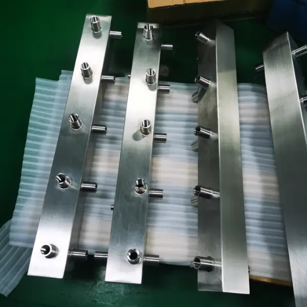
Custom 316L stainless steel water manifold

Drawing-Based Manufacturing

Custom Water Manifold Manufacturing

Weldo manufactures Custom Water Manifolds from your drawings for reliable fluid distribution.

Request a Custom Quote
CNC machined passages Custom port layouts Documented inspection

Structural Types

Water Manifold Types by Core Structure

Select the structure from passage geometry, flow capacity, material, production volume and service requirements.
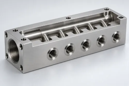
CNC-machined block water manifold 01

CNC-Machined Block Manifold

A one-piece manifold machined from solid plate or billet with intersecting internal passages.

  • Erscheinungsbild Compact rectangular body with dense threaded ports and machined sealing faces.
  • Optimale Verwendung Precision equipment cooling, test systems and low-to-medium-volume custom units.
  • Key control Cross-hole alignment, sealing grooves, port position and internal deburring.
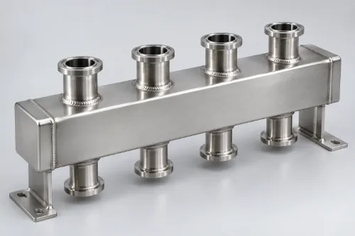
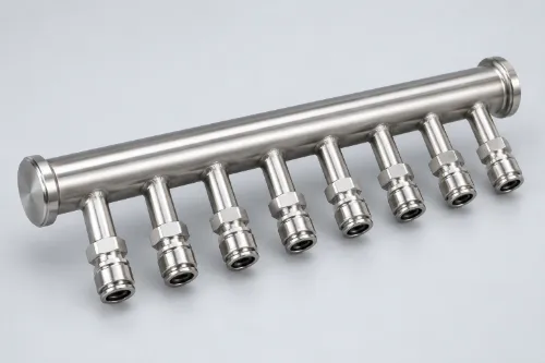
Tubular header water manifold 02

Tubular Header Manifold

A main header tube distributes or collects fluid through multiple connected branches.

  • Erscheinungsbild Long round or rectangular header with evenly spaced outlet necks or quick-connect ports.
  • Optimale Verwendung High-flow in-rack liquid cooling, row distribution, HVAC and industrial cooling.
  • Key control Branch spacing, joint integrity, straightness and pressure-drop control.
Welded stainless steel water manifold assembly 03

Welded Fabricated Manifold

Machined headers, branch necks, end caps and brackets are permanently joined into one assembly.

  • Erscheinungsbild Box or tube-based body with visible joints, mounting feet and configurable connection points.
  • Optimale Verwendung CDUs, process-cooling skids and large or irregular equipment cooling circuits.
  • Key control Weld distortion, joint penetration, passivation and leakage testing.
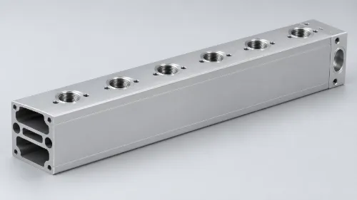
Extruded aluminum water manifold assembly 04

Extruded Profile Manifold

An aluminum extrusion forms continuous longitudinal channels before ports and ends are CNC machined.

  • Erscheinungsbild Long rectangular rail with a constant cross-section and regularly machined branch ports.
  • Optimale Verwendung Repeat-volume rack, battery and power-electronics cooling systems.
  • Key control Profile variation, end sealing, port accuracy and corrosion protection.
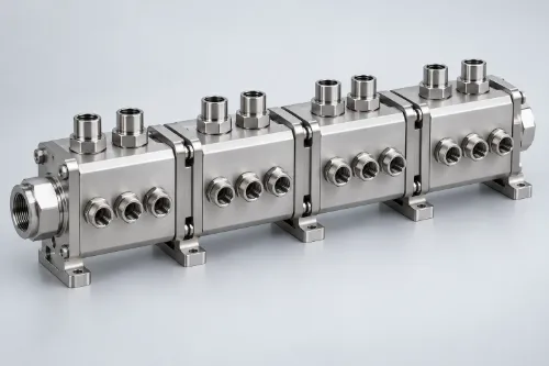
Modular stainless steel water manifold assembly 05

Modular Manifold Assembly

Individual manifold blocks connect through sealed mechanical interfaces to create a configurable system.

  • Erscheinungsbild A repeating row of compact modules with visible joints, ports and mounting features.
  • Optimale Verwendung Expandable data-center racks, laboratory loops and equipment requiring branch replacement.
  • Key control Joint sealing, module alignment, assembly torque and maintenance access.
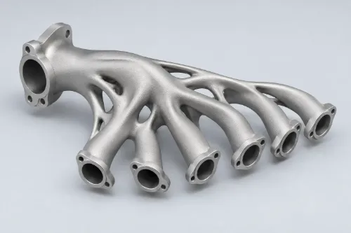
Additively manufactured integrated water manifold 06

Additively Manufactured Manifold

Metal additive manufacturing builds curved internal passages as one integrated component.

  • Erscheinungsbild Compact organic form with smoothly branching outlets and fewer joined components.
  • Optimale Verwendung Space- and weight-critical thermal management and high-value prototype systems.
  • Key control Powder removal, internal surface quality, CT inspection and finish machining.

Anwendungen

Fluid Distribution for High-Value Equipment

Manifold architecture follows the fluid chemistry, operating pressure and flow, cleanliness target and installation environment.

DC Direct-to-Chip Cooling

Data Center Liquid Cooling

In-rack and row-level distribution between CDUs, server racks and cold plates.

IN Industrial

Industrial Equipment Cooling

Cooling circuits for CNC machines, laser systems, test rigs and power electronics.

WT Process Water

Water Treatment Equipment

Controlled distribution for filtration, circulation, dosing and process-water systems.

SC High Cleanliness

Semiconductor Process Cooling

Clean, corrosion-controlled routing for process cooling water and equipment cooling water.

EV Thermal Management

Battery & Energy Systems

Compact coolant routing for battery packs, storage cabinets and charging equipment.

Engineering Inputs

Define the Operating Boundary Before Production

Complete fluid, pressure-flow and interface data gives every critical feature a measurable purpose.

DFM review: wall thickness, passage spacing, tool access, sealing geometry and inspection access.

Fluid

Type, concentration, chemistry, temperature and wetted-material compatibility.

Flow & Pressure

Total and branch flow, working pressure, pressure peaks, back pressure and allowable pressure drop.

Schnittstellen

Port standard, quantity, spacing, orientation, sealing method and mounting datums.

Dienst

Isolation, venting, drainage, monitoring, maintenance access and future expansion.

Materialien und Oberflächen

Match the Material to the Complete Fluid System

Material selection follows coolant chemistry, operating pressure, temperature, weight, cleanliness and joining requirements.

316L

Edelstahl 316L

Improved pitting resistance for more demanding controlled-water service.

Molybdenum improves resistance to chloride-induced pitting compared with 304L. Final approval must consider chloride concentration, temperature, crevice geometry, weld condition and coolant chemistry.

  • Improved pitting resistance
  • Low-carbon weldability
  • High-cleanliness surface capability
SUITABLE ENVIRONMENT

Controlled water or glycol circuits where chloride exposure, humidity or cleanliness requirements exceed the practical range of 304L.

APPLICATIONS

High-density liquid cooling, semiconductor equipment and corrosion-sensitive service.

Fertigungsablauf

CNC Machining Built Around Internal Passage Quality

The approved route connects material control, CNC-Bearbeitung , CNC milling, CNC turning, deep-hole machining, joining, cleaning and verification.

01

DFM & Material Release

Review ports, wall thickness, tool access, sealing geometry and inspection access. Verify the material certificate, grade, condition and blank size, plus any specified visual or nondestructive examination.

02

CNC-Bearbeitung

Mill multi-face geometry, turn cylindrical interfaces, drill controlled passages and finish threads, O-ring grooves and sealing faces.

03

Joining & Finishing

Apply the approved welding, brazing or mechanical assembly route, followed by passivation, electropolishing, anodizing or the specified finish.

04

Deburring & Cleaning

Remove cross-hole burrs, chips, cutting fluid and joining residue. Rinse, dry and protect every fluid-contact passage.

05

Verification & Delivery

Inspect dimensions and complete the approved leakage, pressure, flow or cleanliness tests before controlled packaging.

Weldo Manufacturing Capability

Machining Envelope and Tolerance Capability

Use these ranges for RFQ screening. Material, manifold geometry, feature depth, tool access, fixturing and inspection determine the released capability.

3–5

Multi-Face CNC Milling

Machine external geometry, sealing faces, ports, brackets and intersecting features from controlled datums.

Ø

CNC Turning & Port Machining

Produce concentric end fittings, adapters, threads and sealing interfaces for reliable assembly.

DH

Deep-Hole Passage Control

Plan drilling direction, chip evacuation and cross-hole intersections around internal cleanliness.

QC

Joining & Post-Processing

Support approved welding, brazing, deburring, cleaning, surface treatment and pressure verification.

3000 × 1600 × 1000 mm

Maximum milling envelope

Machine travel; usable size depends on fixturing and tool access.

Ø200 × 1000 mm

Maximum turning capacity

For round bodies, fittings and tubular components.

ISO 2768-f / m

General tolerance classes

Selected by material, nominal size and released drawing.

±0,05 mm

Standard-Maßtoleranz

Applied to quoted machined features unless otherwise specified.

Bis auf ±0,002 mm genau

Ausgewählte Präzisionsmerkmale

Subject to geometry, material, process and inspection review.

0,5 / 1,0 mm

Reference minimum wall

Typical metal / engineering-plastic value after DFM review.

Ra 0,8–3,2 μm

As-machined surface roughness

Feature, cutting direction and material dependent.

Ra 0,8–1,6 μm

Selected sealing-face roughness

Specified from seal type, pressure and leakage requirement.

Port position & orientation O-ring groove geometry Deep-hole drift Cross-hole burr control Joining distortion

Maximum envelope describes machine travel rather than a guaranteed usable part size. ISO 2768 applies only when stated on the drawing; drawing-specific tolerances and GD&T take precedence.

Internal Quality

Inspect What the Finished Exterior Cannot Show

Internal intersections, residual contamination and flow restrictions receive direct controls throughout production.

01

Passage Inspection

Verify deep-hole direction and cross-hole intersections.

02

Internal Deburring

Remove loose burrs from every fluid-contact intersection.

03

Controlled Cleaning

Flush, rinse, dry and seal the completed flow path.

04

Functional Verification

Complete specified pressure, leakage, flow and cleanliness checks.

CMM

Dimensional Report

CMM verification of datums, ports, grooves and sealing relationships.

PT

Pressure & Leakage

Controlled test medium, pressure, temperature and holding time.

FL

Flow & Pressure Drop

Branch performance recorded under defined boundary conditions.

PK

Clean Delivery

Drying, port caps, identification and protective packaging.

Project Workflow

From Drawing Review to Repeat Production

One controlled path connects your operating requirements to production records and final delivery.

  1. 01
    Submit Requirements 2D, 3D, fluid data, interfaces and quantity
  2. 02
    DFM & Process Review Material, machining route, tolerances and tests
  3. 03
    Prototype or First Article Dimensions, interfaces and approved functions
  4. 04
    Kontrollierte Produktion Released programs, tooling and inspection plan

FAQ

Questions Beyond the Manufacturing Overview

What is the difference between a water manifold and a hydraulic manifold?

A water manifold distributes water or coolant through cooling and process circuits. A hydraulic manifold integrates valve cavities and control passages for hydraulic-fluid power and control. Media compatibility, operating pressure, sealing, cleanliness and validation requirements differ by system.

Can Weldo reproduce an obsolete manifold without the original drawings?

Yes. Reverse engineering starts with sample inspection, dimensional capture and interface verification. Operating pressure, fluid, temperature and functional requirements complete the controlled replacement specification.

How are design changes controlled after first-article approval?

Every change receives a controlled drawing revision. Changes to materials, ports, passages, sealing features or testing trigger a new DFM review and the corresponding revalidation.

What documents are supplied with an order?

The purchase specification defines the document package. It includes the requested material certificates, dimensional reports, test records, surface-treatment records and batch traceability.

How should a water manifold be maintained?

Maintenance follows operating data and the approved service plan. Routine checks cover leakage, corrosion, pressure, temperature, flow, filter condition and coolant chemistry. Internal service starts only after isolation, pressure release and drainage.

Can customer-specified valves, sensors and quick disconnects be installed?

Yes. Assembly follows the approved component model, port standard, sealing material, pressure rating, temperature rating and installation procedure.