
Fillet weld welding are commonly used to join custom metal parts such as brackets, bases, frames, and housings. Material, joint design, weld size, and post-weld machining all affect the finished part’s strength, dimensional accuracy, cost, and lead time.

What Is a Fillet Weld Welding? Where Is It Used in Custom Parts?
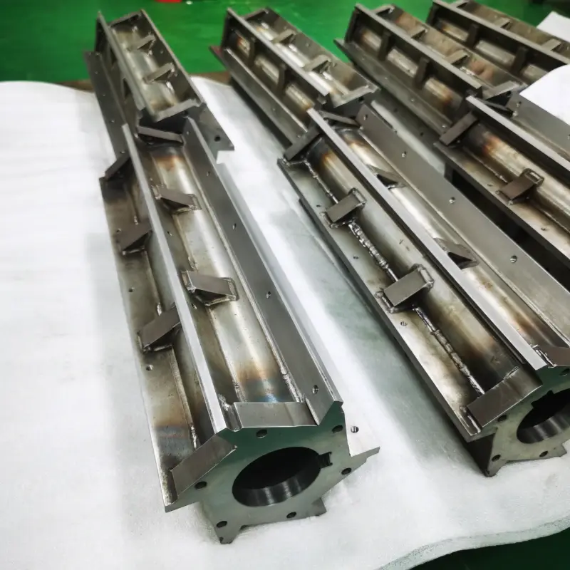
A fillet weld joins intersecting or overlapping metal surfaces and typically has an approximately triangular cross-section. It is commonly used in T-joints, lap joints, and corner joints for equipment brackets, mounting bases, frames, housings, and welded assemblies.
When designing the joint, consider weld access, load direction, and subsequent assembly requirements. For parts with mating holes, sealing surfaces, or CNC machining datums, the drawing should clearly identify the weld location and extent, along with the machining and inspection requirements for those surfaces.
Which Materials Are Commonly Joined with Fillet Welds?
Fillet welds are commonly used on carbon steel, low-alloy steel, stainless steel, and aluminum parts. They can also be used on certain copper alloys, nickel-based alloys, and cast irons. Weld performance depends on the specific grade, material condition, thickness, and process route, so provide these details when requesting a quote.
- Carbon and low-alloy steels: Commonly used for brackets, bases, and frames. Material composition, thickness, and cooling rate affect heat-affected-zone hardness and cracking risk. The supplier should select the filler metal, welding parameters, and preheat requirements accordingly.
- ステンレススチール: Commonly used for corrosion-resistant housings, supports, and equipment components. Welding heat input, filler material, and surface cleanliness affect weld quality and local corrosion resistance. Drawings should specify the grade, service environment, and appearance requirements, with post-weld cleaning specified as needed.
- アルミニウム合金: Commonly used for lightweight brackets, frames, and housings. The heat-affected zone of some heat-treated aluminum alloys can soften locally, so drawings should specify the alloy and supplied condition, as well as post-weld dimensional and performance requirements.
- 銅合金: Commonly used for conductive parts, heat-dissipation components, and some wear-resistant parts. Copper conducts heat quickly, and different alloys have different welding responses and filler-metal requirements. Providing the exact grade and functional requirements helps the supplier determine the process.
- Nickel-based alloys: Commonly used for parts in corrosive, high-temperature, or low-temperature environments. Alloy type affects filler-metal selection, welding process, and post-weld heat treatment. Specify the grade, operating temperature, and contact media when requesting a quote.
- Cast iron: Some cast irons can be welded using specialized processes; gray iron, ductile iron, and other types require separate evaluation. Providing the specific cast-iron type, part function, and loading conditions helps the supplier develop a welding or alternative joining plan.
When Is a Fillet Weld Suitable?
A fillet weld is suitable when the parts have intersecting or overlapping surfaces and the joint’s loading, access, and inspection requirements match the process. It is used for common T-joints, lap joints, and corner joints, particularly when the weld area is accessible.
If the design requires full-thickness penetration, carries high-cycle loads, or requires close control of the weld root, the designer should compare a fillet weld with options such as a groove weld. The decision should account for load direction, part thickness, weld access, and project specifications.
What Are the Advantages and Design Considerations of Fillet Welds?
Fillet welds suit a range of intersecting and overlapping joints, and many designs use straightforward edge preparation that reduces some groove-preparation work. Key design considerations include weld size, loading, weld access, and post-weld dimensional changes.
メリット
- Suitable for many joint configurations: Fillet welds can be used in T-joints, lap joints, and corner joints, making them useful for connecting plates and support components.
- Straightforward joint preparation: Many designs use simple edge preparation, reducing groove-machining operations.
- Flexible placement: Welds can be positioned along the joint to suit a range of custom assemblies.
Design considerations
- Weld size and fit-up gap affect load capacity: Specifying the effective throat based on the load and controlling the joint gap helps achieve the design cross-section.
- The weld root and fatigue performance require evaluation: Provide access for welding and inspection at narrow joints. For parts subject to cyclic loading, assess stress concentration at the weld toe and root.
- Welding heat affects dimensional stability: Suitable fixturing, weld sequencing, and post-weld machining datums help control distortion in thin-walled or asymmetrical parts.
How Do Fillet Welds Differ from Butt Welds or Complete-Joint-Penetration Groove Welds?
A fillet weld joins intersecting or overlapping surfaces, while a butt weld joins members that lie in the same or nearly the same plane. A complete-joint-penetration (CJP) groove weld must achieve the specified penetration through the joint thickness, so the drawing should state this requirement using clear welding terminology and symbols.
Fillet welds generally use more straightforward joint preparation, while groove welds can suit designs requiring a specified penetration depth and joint performance. Select the joint type according to the loading, material, structural access, inspection requirements, and applicable specifications.
Which Parameters Are Commonly Shown on Fillet Weld Drawings?
Drawings should clearly specify the weld location, size, length, and side of the joint to be welded. For intermittent welds, specify the length and spacing of each segment; add contour, surface-treatment, and acceptance requirements according to the part’s function.

| Drawing information | Common callout |
|---|---|
| Weld location | The joint indicated by the arrow, and whether the weld is on the arrow side, other side, or both sides |
| Weld size | Leg length z, throat thickness a, or the dimensioning method specified by the design |
| Weld length | Total length for a continuous weld, or the length of each segment for an intermittent weld |
| Intermittent weld spacing | Center-to-center spacing between adjacent segments, or the spacing defined by the drawing standard |
| Weld contour | Requirements such as flat, convex, or concave; specify when appearance or fatigue performance requires it |
| 検査要件 | Visual, dimensional, and nondestructive testing methods, along with acceptance criteria |
Use the welding-symbol standard specified for the project, such as ISO 2553 or AWS A2.4, consistently for weld locations and dimensions. Production requirements such as material, welding process, filler metal, preheat, and interpass temperature can be included in drawing notes or the applicable WPS. ISO 2553 AWS A2.4
Which Parameters Need to Be Controlled During Fillet Welding?
Fillet weld quality is primarily affected by weld size, joint fit-up, welding parameters, and weld sequence. The manufacturer should set equipment parameters and operating procedures in a welding procedure specification (WPS) suitable for the material, thickness, and joint configuration.
| Process control item | What to control |
|---|---|
| Base material and filler metal | Verify compatibility between the base-metal grade, material condition, and filler metal |
| Joint preparation and positioning | Clean the weld surfaces, control the fit-up gap, and use fixtures to hold the joint in position |
| Welding process | Select the process and set current, voltage, travel speed, wire-feed speed, and shielding gas according to the WPS |
| Heat input and weld sequence | Control preheat, interpass temperature, and weld-pass sequence according to the material and thickness |
| 工程内検査 | Check weld size, surface condition, and critical part dimensions against the drawing |
How Do You Choose Between MIG and TIG Welding?
Both MIG/MAG and TIG can be used for fillet welding. Selection depends on the material, thickness, joint access, appearance requirements, production volume, and cycle time. The process should be evaluated against the part’s function and acceptance requirements.
MIG/MAG is commonly suited to production requiring higher deposition rates, while TIG provides close control of the welding process and suits parts with specific requirements for process control or weld appearance. Filler metal, welding position, and distortion control should also match the selected process.
What Should You Consider During Fillet Welding and for Safety?
Correct welding follows a procedure suited to the material, joint, and thickness, followed by inspection of dimensions and weld quality. Production controls should cover preparation, fixturing, welding, and post-weld inspection.
Before welding, clean the joint and check the material and fit-up gap, then position and tack the parts in a fixture. During welding, follow the WPS for parameters, torch angle, and sequence; for multipass welds, control the pass sequence and interpass conditions as specified. After welding, remove slag and spatter, then inspect the weld’s appearance and dimensions.
Safe work requires spark containment, combustible-material control, suitable eye, face, and body protection, and effective ventilation. For confined spaces or work involving hazardous metal fumes, implement specific ventilation, monitoring, and respiratory-protection measures based on the site risk assessment.
What Post-Weld Treatments Help Maintain Part Performance?
Select post-weld treatments according to the material and technical specifications, focusing on residual stress, corrosion resistance, dimensions, or surface requirements. Final part performance depends on joint design, material compatibility, welding procedure, and defect control, so post-weld treatments should be planned as part of the overall process.
- Carbon and low-alloy steels: Evaluate preheating, interpass-temperature control, or post-weld heat treatment according to the grade, thickness, joint restraint, and project specification. Post-weld heat treatment can reduce and redistribute some residual stresses; set the temperature and hold time according to the material and process requirements.
- ステンレススチール: Remove slag, spatter, and heat tint according to the surface and corrosion-resistance requirements, then apply pickling or 不動態化 where specified for the grade. Passivation improves the surface passive condition; joint design and welding procedure control the weld’s mechanical performance.
- アルミニウム合金: Welding thermal cycles affect the properties of the heat-affected zone in some heat-treated aluminum alloys. Evaluate post-weld aging or other heat treatments according to the alloy, supplied condition, and product requirements.
- Precision assemblies: Recheck critical datums and distortion after welding, then schedule CNC finishing, surface protection, and final inspection. When nondestructive testing is specified, include the inspection timing and post-repair reinspection requirements in the technical agreement.

How Does Welding Distortion Affect Custom-Part Dimensions and Subsequent CNC Machining?
Welding heat causes local expansion and contraction, which can affect hole positions, flatness, angles, and assembly datums. For precision assemblies, plan the welding, heat-treatment, and CNC-machining sequence in advance, and reserve sufficient stock for post-weld machining.
Thin-walled, long, or asymmetrical parts require particular attention to fixturing and weld sequence. Re-measure critical datums after welding, then machine mating surfaces, holes, and sealing faces; evaluate stress-relief treatment according to the material, part dimensions, and drawing requirements.
What Are Common Fillet Weld Defects and Inspection Methods?
Fillet weld acceptance mainly involves checking weld size, surface condition, and the quality requirements specified on the drawing. Visual and dimensional inspections confirm the weld’s surface and geometry; other inspection methods are selected according to the material, joint configuration, thickness, and acceptance specification.
- Lack of fusion: The weld metal has not fused adequately with the base metal or a previous weld pass. Clean the joint before welding and control heat input, torch angle, and travel speed according to the procedure; for repair, remove the defect and reweld using an approved procedure.
- Porosity: Gas trapped in the weld pool during solidification forms pores. Before welding, remove oil, water, rust, and coatings that affect weld quality, and check the shielding gas, gas lines, and wind protection around the welding area.
- Undercut: A groove forms at the weld toe and can affect weld profile and fatigue performance. Adjust current, travel speed, and torch angle according to the procedure; inspect the weld against the acceptance criteria and arrange repairs as required.
- Cracks: First establish the extent and cause of the crack, then remove it and reweld using an approved repair procedure. Perform the specified reinspection after repair to verify weld quality.
- Overlap: Weld metal extends onto the base-metal surface without adequate fusion. Improve the weld profile by controlling the weld pool, torch angle, and travel speed; handle repair areas according to the drawing and procedure.
- Insufficient leg length or throat thickness: Dimensions below the drawing requirements reduce the effective load-bearing section. Recheck the weld dimensions and measurements, then add weld metal and reinspect according to a repair plan approved by the design authority.
- Excessive fit-up gap: The joint gap affects the effective leg length or throat thickness. Use fixtures to control the fit-up gap before welding; if a deviation occurs, the design or process engineer should confirm the compensation plan and acceptance requirements.
Magnetic particle testing is suitable for surface and near-surface defects in ferromagnetic materials, while penetrant testing can detect surface-breaking defects. Confirm the inspectability of the fillet weld root, internal inspection method, and acceptance criteria before production, and include them in the technical agreement.
How Can You Control the Cost and Lead Time of Fillet-Welded Parts?
Weld size and length, joint access, setup count, distortion control, post-weld machining, and inspection requirements all affect cost and lead time. Complete drawings and acceptance requirements help the manufacturer plan the production route efficiently.
Set weld dimensions according to functional loads, optimize weld access and fixtures, and reduce repeated setups. Define post-weld machining surfaces, critical dimensions, and inspection documents in advance. Validating fit and post-weld dimensions at the sample stage helps stabilize batch production.
How Do You Evaluate a Custom-Part Welding Supplier?
A supplier should be able to review the joint design, establish a welding procedure, and control weld distortion and post-weld dimensions. For assemblies requiring CNC finishing, the welding datums, machining allowance, and inspection plan should be coordinated within one manufacturing route.
During supplier review, confirm that the supplier has procedure documentation suitable for the material and joint, and can provide welder qualifications, material traceability, process records, and inspection reports as required by the project. WPS, certification, and documentation requirements are determined by the contract, applicable industry specifications, and customer standards.
For a quote, provide 2D drawings, 3D models, material grade, quantity, weld locations and dimensions, post-weld machining requirements, and acceptance criteria. This information allows the manufacturer to evaluate joint manufacturability, distortion control, inspection scope, and lead time.
よくあるご質問
What Is the Difference Between a Fillet Weld and a Complete-Joint-Penetration Groove Weld?
A fillet weld joins intersecting or overlapping surfaces, while a complete-joint-penetration groove weld must achieve the penetration specified in the design. The two options require different joint preparation, manufacturing routes, and inspection requirements, so select according to the loading, structure, and applicable specifications.
Does a Larger Fillet Weld Always Make the Joint Stronger?
Joint strength depends on the design load, effective throat, material, and weld quality. Properly specified weld dimensions meet the load requirements while controlling material use and thermal distortion.
Can Custom Parts Be CNC Machined After Welding?
Yes. Plan the manufacturing route around weld distortion, locating datums, and machining allowance, then remeasure the part after welding before machining critical holes, mating surfaces, or sealing faces.
What Information Should a Fillet Weld Drawing Include?
The drawing should specify weld location, size, length, weld side, continuous or intermittent requirements, the applicable symbol standard, and acceptance criteria. Post-weld machining and inspection requirements should also be included.
Which Inspection Methods Are Suitable for Fillet Welds?
Visual and dimensional inspections confirm the weld surface and geometry. Magnetic particle or penetrant testing can be selected for surface or near-surface indications according to the material and defect type; internal inspection methods are selected according to the joint configuration and acceptance specification.
When a custom part combines a welded structure with precision-machined surfaces, submit the drawing, material, quantity, weld requirements, and critical dimensions together. This helps coordinate welding, CNC加工, inspection, and delivery.