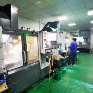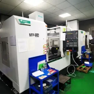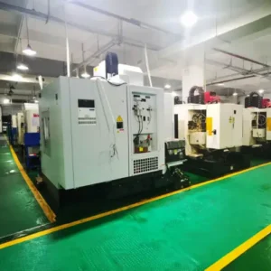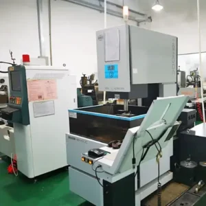

Cylindrical grinding is used to finish shafts and other rotationally symmetrical parts. It controls outside diameter, roundness, cylindricity, runout, and surface roughness.
In a standard manufacturing sequence, CNC turning establishes the basic geometry, heat treatment gives the part its required hardness, and cylindrical grinding completes the final bearing seats, sealing surfaces, and sliding surfaces.
Cylindrical grinding is not simply a matter of reducing a diameter. Workholding datums, wheel condition, grinding parameters, temperature, and inspection methods all affect the final result.
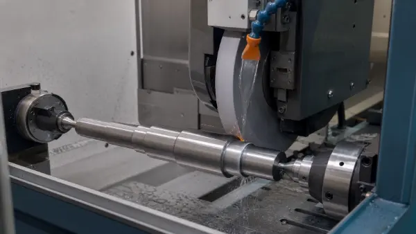
What Is Cylindrical Grinding?
In cylindrical grinding, the workpiece rotates about its own axis while a high-speed grinding wheel removes material through radial or longitudinal feed.
The abrasive grains on the wheel act as thousands of microscopic cutting edges. Each grain passes through rubbing, plowing, and cutting before producing a small chip.
When the wheel becomes dull or the process parameters are incorrect, the proportion of rubbing increases. Grinding force and temperature rise as a result, leading to chatter, grinding burn, and dimensional variation.
Main Types of Cylindrical Grinders
- External cylindrical grinder: Machines outside cylindrical surfaces such as shafts, piston rods, and bearing seats.
- Internal cylindrical grinder: Machines precision bores in sleeves, gears, and bearing housings.
- Universal cylindrical grinder: When equipped with an internal grinding attachment and a swiveling wheelhead, it can grind outside diameters, inside diameters, tapers, and end faces.
- Centerless grinder: Supports the workpiece between a grinding wheel, regulating wheel, and work-rest blade. It is suited to batch production of pins, rollers, and round bar.
- CNC cylindrical grinder: Suited to stepped shafts, tapers, radii, and complex surfaces of revolution.
- Roll grinder: Used for large rolls, long shafts, and compensated roll profiles.
Characteristics of OD Grinding
OD grinding is short for outside diameter grinding. It machines the external rotational surfaces of a part.
Typical parts include motor shafts, gear shafts, piston rods, pump shafts, valve spools, precision arbors, and bearing seats.
Workpieces can be located between centers, in a chuck, on a mandrel, or in a dedicated fixture. Precision long shafts are commonly ground between centers with steady-rest support to control deflection.
When grinding between centers, the center holes form the rotational datum. Their roundness, position, and taper contact directly affect every ground journal.
What Shapes Can Cylindrical Grinding Produce?
A cylindrical grinder does more than grind straight outside diameters. Wheel dressing, table adjustment, and CNC interpolation allow it to produce several rotational profiles.
Straight Cylindrical Surfaces
A straight cylindrical surface is the most common ground geometry.
Key requirements are diameter, roundness, cylindricity, and surface roughness. Typical parts include guide shafts, piston rods, pins, valve spools, and bearing seats.
Stepped Shafts and Shoulders
A stepped shaft contains several diameters and axial locations.
All journals should share a consistent rotational datum. The wheel edge must also be dressed to match the shoulder, relief groove, and fillet requirements and prevent assembly interference.
Tapered Surfaces
Tapers are ground by swiveling the table, adjusting the wheelhead, or using CNC interpolation.
Key requirements include taper angle, generating-line straightness, effective contact position, and rotational datum. Typical features include spindle tapers, toolholder locating surfaces, and valve-spool sealing surfaces.
Radii and Contoured Surfaces of Revolution
A CNC cylindrical grinder can produce fillets, concave profiles, convex profiles, and continuous blends.
These features are surfaces of revolution formed around the workpiece axis. The grinding-wheel profile must match the target curve.
Spherical Surfaces
Spherical grinding is used for ball ends, spherical valve elements, and precision locating features.
The process must control sphere diameter, profile error, and surface quality. The transition between the spherical and cylindrical surfaces should remain smooth.
Eccentric and Non-Circular Profiles
CNC grinders with synchronized control can machine eccentric shafts, cams, and crankshaft journals.
The process synchronizes workpiece angle with wheel position. Inspection covers eccentricity, phase angle, and the actual profile.
Compensated Roll Profiles
Large rolls can be ground to straight cylindrical, crowned, concave, or segmented compensation profiles.
The profile should be designed around working load, temperature, and the actual contact zone rather than unloaded diameter alone.
How Does Cylindrical Grinding Compare with CNC Turning?
CNC-Drehen and cylindrical grinding both machine rotational parts, but they perform different manufacturing tasks.
CNC turning removes material quickly and establishes the geometry. Cylindrical grinding controls final dimensions, geometric accuracy, and surface quality after heat treatment.
| Vergleich | CNC-Drehen | Zylinderschleifen |
| Cutting principle | A cutting tool removes material from a rotating workpiece | A grinding wheel removes material from a rotating workpiece |
| Primary purpose | Roughing, semi-finishing, and profile generation | Final finishing after heat treatment |
| Removal rate | Larger depth of cut per pass | Smaller material removal per pass |
| Dimensional control | Suited to standard fit tolerances | Suited to tight diameter tolerances |
| Geometrische Genauigkeit | More strongly affected by cutting force and workholding | Better suited to controlling roundness and cylindricity |
| Surface condition | Leaves turning feed marks | Produces a fine, uniform grinding pattern |
| Material hardness | Conventional turning is mainly used before hardening | Suited to hardened steels and hard coatings |
| Komplexe Merkmale | Suited to threads, deep grooves, and complex profiles | Suited to precision diameters, tapers, and shoulders |
| Process preparation | Programming and tool changes are direct | Requires wheel balancing and dressing |
| Bearbeitungskosten | Lower for ordinary accuracy requirements | Higher precision and inspection cost |
Advantages of CNC Turning
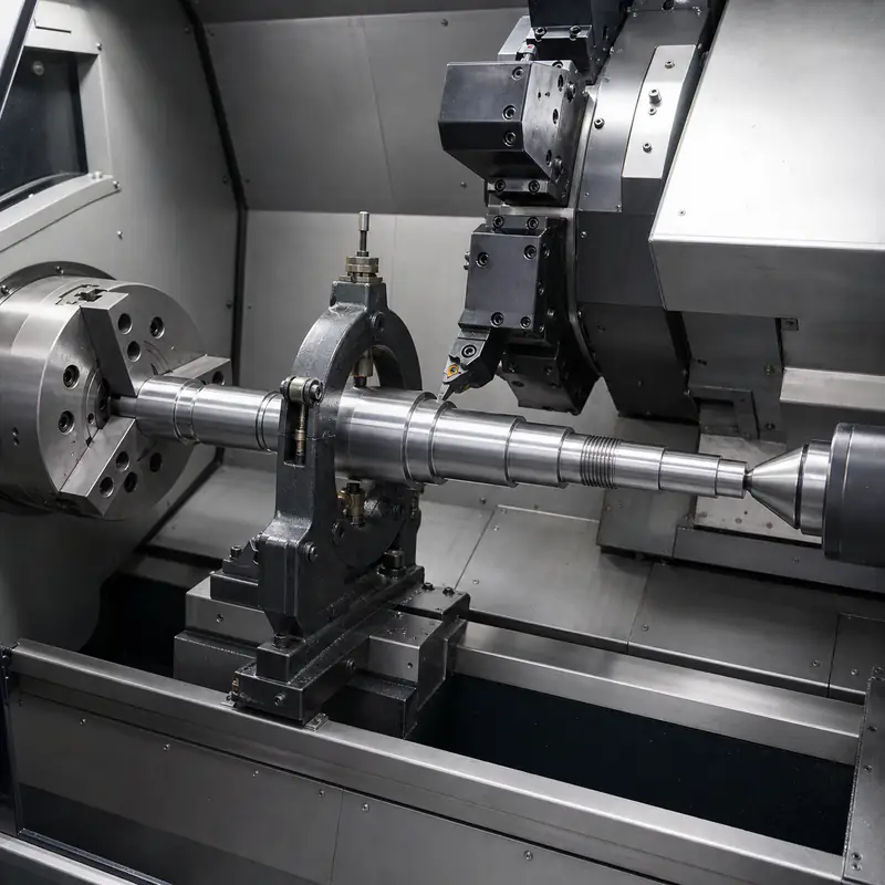
CNC turning removes material quickly. It efficiently machines outside diameters, end faces, grooves, threads, and radii.
A wide range of standard cutting tools is available. Parts with ordinary dimensional and surface requirements do not require an added grinding operation.
Limitations of CNC Turning
Cutting force can bend slender shafts and generate vibration. Workholding error also affects roundness and rotational runout.
Turning leaves helical feed marks. Some sealing surfaces, high-speed journals, and precision sliding surfaces cannot be used directly after turning.
Hard Turning and Cylindrical Grinding
With CBN or ceramic cutting tools, CNC lathes can machine selected hardened steels.
Hard turning is effective for producing profiles and interrupted features on hardened parts. Cylindrical grinding provides more stable control of tight roundness, continuous precision surfaces, and low roughness.
Advantages of Cylindrical Grinding
Cylindrical grinding corrects dimensions and minor distortion after heat treatment.
It is better suited to controlling roundness, cylindricity, and runout while producing a uniform precision surface.
Limitations of Cylindrical Grinding
Cylindrical grinding is not intended to remove large amounts of stock directly from a blank.
The wheel must be selected, balanced, and dressed correctly. Coolant, temperature, and measurement conditions must also remain stable.
When Should You Choose Cylindrical Grinding?
Adding a grinding operation increases manufacturing cost. The decision should therefore be based on part function and drawing requirements.
Dimensions Must Be Corrected After Heat Treatment
Hardening, carburizing, and nitriding change dimensions and introduce slight distortion.
Cylindrical grinding restores journal size, roundness, and runout after heat treatment. Typical parts include gear shafts, bearing shafts, and hardened pins.
Geometric Tolerances Are Tight
When a part has strict requirements for diameter, roundness, cylindricity, or runout, cylindrical grinding should complete the final operation.
Improving turning size control cannot replace grinding when the overall form must be corrected.
The Surface Provides Sealing or Sliding
Seal journals, piston rods, valve spools, and guide surfaces require a uniform surface texture.
Cylindrical grinding reduces the effect of helical turning marks on sealing, lubrication, and sliding performance.
The Part Rotates at High Speed
Motor shafts, machine spindles, rotor shafts, and reducer shafts are highly sensitive to runout.
A ground journal gives the bearing a stable datum and reduces vibration, noise, and localized heating at high speed.
Several Journals Must Share One Datum
Stepped shafts, gear shafts, and transmission shafts contain several fitted diameters.
Grinding multiple journals from a common datum improves the rotational relationship between bearing seats, gear seats, and sealing surfaces.
A Worn Journal Requires Repair
A worn shaft can be rebuilt by chrome plating, thermal spraying, or weld deposition.
After the coating is applied, cylindrical grinding restores the final diameter, profile, and surface quality.
Batch Parts Require Consistent Results
Pins, rollers, piston rods, and automotive shafts require a stable dimensional distribution.
A controlled wheel, dressing interval, measurement frequency, and size-compensation strategy reduce variation between batches.
When Cylindrical Grinding Should Not Be the First Operation
- The blank has a large amount of stock to remove.
- The basic part geometry is not complete.
- Threads, deep grooves, or non-rotational features must be produced.
- Standard dimensional tolerances already satisfy the functional requirement.
- The workpiece has no reliable rotational datum.
- Workholding distortion in a thin-walled part has not been resolved.
A sound process sequence is to establish the shape by turning, obtain the required properties through heat treatment, and finish the critical surfaces by cylindrical grinding.
Cylindrical Grinding Operating Procedure
Cylindrical grinding should follow a fixed sequence. The essential actions are to confirm the datum, stabilize the wheel condition, divide the infeed into stages, and measure at the correct intervals.
1. Confirm the Machining Requirements
Review the drawing, material, and heat-treatment condition.
Confirm diameter tolerance, roundness, cylindricity, runout, roughness, shoulder location, fillets, and grinding allowance.
2. Inspect and Warm Up the Machine
Inspect the spindle, table, workhead, tailstock, guarding, and coolant system.
Warm up the machine before precision grinding so the spindle, guideways, and feed system reach a stable condition.
3. Select and Mount the Grinding Wheel
Select the wheel according to workpiece material, hardness, contact area, and surface requirement.
Before mounting, check the wheel specification, condition, and rated speed. Balance it and complete an unloaded trial run after mounting.
4. Dress the Grinding Wheel
Dress the wheel periphery, side, and corner radius.
For stepped shafts, tapers, and radii, verify the actual wheel profile. The dresser position and rigidity must also remain stable.
5. Load the Workpiece
Select between-center mounting, a chuck, a mandrel, or a dedicated fixture according to the part geometry.
Clean the center holes before between-center grinding. Support slender shafts with a steady rest or follower rest.
6. Align the Datum
Use a dial indicator to check runout at the outside diameter, end face, and datum locations.
Adjust the workhead, tailstock, and supports so the rotational axis is aligned with the machine grinding direction.
7. Set the Grinding Parameters
Set wheel surface speed, workpiece speed, longitudinal feed, radial infeed, table travel, and coolant flow.
Allocate stock for rough grinding, semi-finishing, finishing, and spark-out.
8. Start Coolant and Make a Trial Grind
Establish a stable coolant stream at the grinding zone before the wheel contacts the workpiece.
Make a light trial grind to verify contact, rotation direction, and coolant coverage. Measure the diameter and correct the coordinate or infeed value.
9. Rough Grind
Rough grinding removes most of the stock.
Use several infeed passes rather than one heavy cut. Monitor sparks, sound, vibration, and coolant condition.
10. Semi-Finish
Leave a uniform finishing allowance after rough grinding.
Semi-finishing corrects taper, roundness, and local high spots. Measure both ends and the center afterward.
11. Finish Grind and Spark Out
Reduce the radial infeed during finishing and approach final size gradually.
Near final size, stop radial infeed and complete the programmed spark-out passes. Spark-out removes local high spots and releases elastic deflection in the machine, fixture, and workpiece.
Spark-out cannot correct an incorrect workholding datum or a severe taper error.
12. Perform Final Inspection
After the workpiece temperature stabilizes, inspect outside diameter, roundness, cylindricity, taper, circular or total runout, shoulder location, fillet profile, surface roughness, burn, cracks, and scratches.
Measure long shafts at both ends and at the center.
13. Clean and Record
After grinding, clean the workpiece, centers, fixture, and grinding debris from the machine.
For batch production, record wheel specification, number of dress cycles, grinding parameters, size compensation, and inspection results.
Key Cylindrical Grinding Parameters
Wheel speed, workpiece speed, and feed settings together determine material removal rate, grinding temperature, and surface quality.
Grinding-Wheel Surface Speed
Wheel surface speed determines how quickly abrasive grains pass through the grinding zone.
The speed must remain below the maximum marked on the wheel. Excessive speed creates a wheel-safety hazard, while insufficient speed reduces cutting efficiency and changes the surface condition.
Werkstückgeschwindigkeit
Workpiece speed affects the load on each abrasive grain and the texture left on the surface.
Excessive speed increases grinding load. Insufficient speed reduces productivity and increases local grinding time.
Radial Infeed
Radial infeed determines the thickness of material removed in each pass.
A larger infeed increases removal rate but also raises grinding force, temperature, and burn risk. Finishing requires a smaller infeed.
Longitudinal Feed and Overlap
Longitudinal feed determines how quickly the wheel moves along the workpiece axis.
Correct overlap produces a uniform surface. Excessive feed leaves pronounced spiral marks and reduces the consistency of cylindricity and roughness.
Spark-Out Passes
No additional radial infeed is applied during spark-out.
A controlled spark-out improves roundness and surface quality. Excessive spark-out reduces productivity and increases non-cutting friction.
Wheel-Dressing Parameters
Dressing depth, traverse speed, and dressing interval alter wheel cutting behavior.
A finer dress produces a smoother wheel surface. A coarser dress increases cutting ability but also increases surface roughness.
What Accuracy Parameters Must Cylindrical Grinding Control?
A diameter tolerance controls size but does not fully define the form and rotational accuracy of a shaft.
A precision journal must also be controlled through the following characteristics:
- Diameter tolerance: Determines the fit with bearings, seals, and sleeves.
- Roundness: Limits form error within an individual cross-section.
- Cylindricity: Controls the combined form error over the entire cylindrical surface.
- Straightness: Limits bending of a long generating line or axis.
- Circular runout: Indicates variation at one location during one workpiece revolution.
- Total runout: Evaluates combined variation over the entire cylindrical surface relative to the datum axis.
- Taper angle and taper: Control locating depth and contact condition on a tapered surface.
- Profile tolerance: Limits the actual deviation of radii, spheres, and formed surfaces.
- Oberflächenrauheit: Affects friction, sealing, lubrication, and fatigue life.
- Heat-treatment hardness: Determines wheel selection, feed settings, and thermal-damage risk.
On high-precision equipment, typical OD grinding diameter tolerances can range from ±10 μm down to less than ±1 μm, while roundness can reach 0.25–2.5 μm.
The actual capability must be confirmed against part diameter, length-to-diameter ratio, material, workholding, temperature control, and inspection equipment. These figures are process references, not an unassessed manufacturing commitment.
Messmethoden
A micrometer measures outside diameter but does not replace roundness measurement.
Roundness requires a roundness tester or an equivalent rotational measurement system. Cylindricity must cover several cross-sections and axial positions. Runout must be measured from the datum specified on the drawing.
Surface Integrity
Precision grinding requires more than dimensional and roughness inspection. Grinding burn, microcracks, residual stress, and changes in surface hardness must also be considered.
For hardened shafts, aerospace components, and high-speed rotating parts, the absence of visible discoloration does not prove that the surface is free from thermal damage.
Critical parts can be verified through hardness testing, magnetic-particle inspection, penetrant inspection, or a dedicated grinding-burn detection method.
Common Cylindrical Grinding Problems and Solutions
Grinding problems should be investigated in sequence: locating datum, wheel condition, process parameters, coolant, and machine condition.
Roundness Out of Tolerance
Main causes:
- Center holes contain burrs, wear, or positional error.
- The workhead and tailstock centers are not coaxial.
- The wheel is out of balance.
- Workpiece support is unstable.
- The spindle or guideway condition is abnormal.
Lösung:
Clean and restore the center holes and inspect center contact. Rebalance and dress the wheel, then reduce the final infeed. Add suitable support for a slender shaft.
Taper Error
Main causes:
- The workhead and tailstock axes are not parallel.
- The table angle is incorrect.
- The wheel has localized wear.
- Coolant distribution differs between the two ends.
- Support conditions are inconsistent.
Lösung:
Align the workhead, tailstock, and table with a test bar. Redress the wheel and maintain uniform coolant coverage.
Chatter Marks
Main causes:
- The wheel is poorly balanced.
- Workpiece speed excites resonance.
- The fixture or steady rest lacks rigidity.
- The wheel specification does not match the application.
- The wheel spindle condition is abnormal.
Lösung:
Rebalance and dress the wheel. Adjust workpiece speed and feed, then inspect the fixture, centers, and spindle.
Grinding Burn or Discoloration
Main causes:
- The infeed per pass is too large.
- The wheel is dull or loaded.
- The wheel grade is too hard.
- Coolant coverage is inadequate.
- Too much stock remains for finishing.
Lösung:
Reduce the infeed, sharpen the wheel by dressing, and improve coolant coverage. A burned part must also be checked for hardness change and cracking.
Surface Roughness Out of Specification
Main causes:
- The wheel grit is too coarse.
- Dressing parameters are inconsistent.
- Finishing infeed is too high.
- Spark-out is insufficient.
- The coolant contains grinding debris.
Lösung:
Select a suitable finishing grit, stabilize dressing, reduce final infeed, and apply the required spark-out passes.
Continuous Size Drift
Main causes:
- Machine and workpiece temperatures are unstable.
- The wheel is wearing continuously.
- Size compensation is incorrect.
- Measurement conditions are inconsistent.
- The dressing interval is too long.
Lösung:
Warm up the machine, standardize measurement temperature, and establish controlled dressing and size-compensation intervals.
Slender-Shaft Bending
Main causes:
- Tailstock pressure is too high.
- Support position is incorrect.
- Grinding force is concentrated locally.
- Residual stress is being released.
- Cooling is uneven.
Lösung:
Adjust tailstock pressure and steady-rest position. Reduce infeed and complete stress relief and straightening after pre-machining.
Wheel Loading
Main causes:
- Soft workpiece material adheres to the wheel.
- Wheel structure is too dense.
- Wheel grade is too hard.
- Coolant filtration is inadequate.
Lösung:
Use an open-structure, free-cutting wheel. Dress more frequently and improve coolant filtration.
Spiral or Traverse Marks
Main causes:
- Longitudinal feed is too fast.
- The wheel edge is dressed incorrectly.
- The wheel is not aligned with table travel.
- Overlap is incorrect.
Lösung:
Reduce longitudinal feed, correct overlap, and redress the wheel.
Cylindrical Grinding Process Considerations
Effective process control reduces rework, grinding burn, and dimensional variation.
Distribute Grinding Allowance Evenly
Excessive stock increases grinding heat. Insufficient stock cannot remove turning marks, scale, or heat-treatment distortion. The pre-heat-treatment allowance must also cover the decarburized layer and expected distortion.
Straighten Before Grinding
A bent long shaft should be straightened first. Grinding a bent blank directly creates uneven stock and localized heating.
Use a Consistent Machining Datum
Turning, post-heat-treatment straightening, and grinding should use a consistent datum system. Where practical, finish multiple journals in one setup.
Maintain Sound Center Holes
Before between-center grinding, check the center-hole taper, roundness, and cleanliness. When the center holes are defective, wheel and feed adjustments alone cannot stabilize roundness.
Select the Wheel Correctly
Abrasive type, grit size, grade, structure, and bond must match the material and process target. A large contact area requires effective chip clearance and heat dissipation. Fine surfaces require stable dressing and suitable grit.
Keep Dressing Conditions Consistent
Dressing depth, traverse speed, and interval should remain consistent. Excessive dressing increases wheel consumption, while insufficient dressing causes dulling, loading, and burn.
Maintain Stable Coolant
Grinding fluid provides cooling, lubrication, cleaning, and chip removal. The nozzle must deliver a continuous stream into the wheel-workpiece interface. Inadequate filtration causes scratches, roughness variation, and wheel loading. Tight dimensional work also requires stable coolant and inspection temperatures.
Approach Final Size in Stages
Roughing, semi-finishing, and finishing require a defined stock distribution. Reduce infeed near final size and use spark-out to release elastic deflection.
Support Slender Shafts
Position a steady rest or follower rest close to the grinding zone. Excessive support force changes the natural workpiece axis, while insufficient support cannot suppress vibration.
Protect Shoulders and Fillets
The wheel edge must match the shoulder, relief groove, and fillet requirements. A fillet that is too small creates stress concentration, while an oversized fillet interferes with a bearing, gear, or sleeve.
Standardize Inspection Conditions
Measure diameter, roundness, and roughness after temperature stabilization. Measurement location, direction, instrument, and datum must remain consistent.
Workpiece Materials and Grinding-Wheel Selection
Cylindrical grinding covers hardened steels, stainless steels, light alloys, superalloys, and coated parts.
Common Workpiece Materials
- Carbon and alloy steels: Used for transmission shafts, gear shafts, and hydraulic rods.
- Bearing steel: Used for races, rollers, and hardened journals.
- Tool and die steels: Used for arbors, guide posts, punches, and die fits.
- Rostfreier Stahl: Used for valve spools, pump shafts, and medical components.
- Cast iron: Used for sleeves, machine components, and large rolls.
- Aluminium-Legierungen: Used for lightweight sleeves and rollers.
- Copper alloys: Used for bushings, conductive shafts, and wear components.
- Titanium alloys: Used for aerospace and medical shafts.
- Nickel-based alloys: Used for high-temperature equipment and energy components.
- Cemented carbide: Used for precision arbors, gauges, and wear parts.
- Chrome-plated and thermally sprayed parts: Used for piston rods and worn-shaft repair.
Common Abrasive Types
- Aluminum oxide wheels: Suited to carbon steel, alloy steel, and conventional hardened steel.
- Silicon carbide wheels: Suited to cast iron, selected non-ferrous metals, and non-metallic materials.
- CBN wheels: Suited to high-hardness tool steel, bearing steel, and selected superalloys.
- Diamond wheels: Suited to cemented carbide, ceramics, and selected non-ferrous materials; they are not used for conventional grinding of ordinary steels.
Wheel selection cannot be based on abrasive type alone. Grit size, grade, structure, bond, and dressing method also affect the result.
Typical Cylindrical Grinding Applications
Cylindrical grinding is widely used in automotive, hydraulic, bearing, aerospace, tooling, and large industrial roll applications.
Automotive Component Grinding
Automotive component grinding is precision grinding for engine, transmission, steering, suspension, and electric-drive components.
- Motor rotor shafts
- Transmission input and output shafts
- Gear shafts
- Camshafts
- Crankshaft journals
- Steering shafts
- Shock-absorber piston rods
- Pump shafts and valve spools
- Electric-vehicle reducer shafts
Automotive shafts require control of bearing seats, sealing surfaces, gear seats, and rotational runout. Batch production also requires fixed dressing intervals, measurement frequency, and compensation rules.
Hydraulic and Sealing Components
Hydraulic piston rods, plungers, valve spools, and pump shafts require stable diameter, roundness, and surface texture.
An overly rough surface accelerates seal wear. A strongly directional texture can also form a leakage path.
Bearing and High-Speed Rotating Components
Bearing seats, spindles, and rotor shafts require controlled roundness, journal size, and relative runout.
Error causes uneven bearing loading and increases vibration, noise, and localized heating.
Roll Grinding Service
Roll grinding service is specialized cylindrical grinding for long shafts and large rolls.
- Mill rolls
- Printing rolls
- Paper-machine rolls
- Film rolls
- Coating rolls
- Conveyor rolls
- Calender rolls
- Rubber-roll cores
Roll grinding controls not only diameter but also full-length straightness, cylindricity, runout, and compensated profile.
Crowned or concave rolls should be profiled according to working load. Large-roll projects must also address load capacity, dynamic balance, and transport protection.
Safety Rules for Cylindrical-Grinding Operators
Operators must be trained in the machine, grinding wheels, and safeguarding. Each company should establish written procedures based on the equipment manual and local regulations.
Before Starting Work
- Know the locations of the emergency stop and energy-isolation controls.
- Wear safety glasses and safety footwear.
- Add a face shield where flying debris presents a risk.
- Secure long hair and close loose cuffs.
- Do not wear rings, bracelets, or other items that can become entangled.
- Do not bring gloves near rotating components.
Pre-Start Inspection
- Check wheel type, dimensions, and rated speed.
- Do not exceed the wheel’s maximum permitted speed with the machine spindle.
- Inspect the wheel, flanges, blotters, and fastening condition.
- Perform the specified ring test on applicable vitrified-bond wheels.
- Check the guard and safety interlocks.
- Confirm that the workpiece, centers, fixture, and steady rest are locked.
- Remove tools and measuring instruments from the machine enclosure.
Abrasive-wheel machinery must have suitable safeguarding. The wheel must also be checked for damage and rated speed before mounting.
Wheel Trial Run
- Run the wheel unloaded with the guard closed.
- Do not stand directly in the plane of wheel rotation.
- Check for abnormal sound, vibration, and spindle temperature rise.
- Stop immediately when an abnormal condition appears.
- Do not resume grinding until the cause has been identified.
During Grinding
- Start an automatic cycle only with the guard door closed.
- Use a low infeed when the wheel first contacts the workpiece.
- Do not touch a rotating workpiece, wheel, or fixture.
- Do not reach across a rotating workpiece to measure it.
- Do not adjust centers or steady rests while the wheel is rotating.
- Stop immediately if coolant is interrupted, the workpiece becomes loose, or abnormal vibration occurs.
Measurement and Adjustment
- Retract the wheel from the grinding zone before measurement.
- Wait for the workpiece and wheel to stop completely before manual measurement.
- Shut down the relevant power before adjusting fixtures and supports.
- Apply energy isolation before maintenance or removal of a jam.
- Never stop the wheel, chuck, or workpiece by hand.
Shutdown and Maintenance
- Wait for the wheel to stop completely before opening the guarded area.
- Remove debris with a brush, scraper, or extraction system.
- Do not remove sharp swarf with bare hands.
- Disconnect power before changing a wheel.
- Do not operate with a damaged guard or safety interlock.
The HSE guidance on abrasive-wheel safety also emphasizes operator training, correct mounting, guarding, and adjustment only after shutdown.
How to Choose a Cylindrical Grinding Supplier
Supplier selection should focus on equipment, workholding, inspection, and process control.
- Work envelope: Confirm maximum diameter, effective grinding length, and workpiece weight.
- Prozessbereich: Confirm external, internal, taper, face, and form-grinding capability.
- Workholding: Check between-center, chuck, mandrel, and steady-rest capability.
- Wheel management: Confirm that wheel selection, balancing, dressing, and replacement are controlled.
- Material experience: Verify experience with hardened steel, stainless steel, titanium alloys, and coated parts.
- Fähigkeit zur Inspektion: In addition to diameter, the supplier should measure roundness, runout, profile, and roughness.
- Surface integrity: Critical parts require a defined method for grinding-burn, crack, or hardness inspection.
- Long-shaft control: Slender shafts require a clear support, straightening, and temperature-control plan.
- Process records: Batch parts should have first-piece, in-process, and final inspection records.
- Process coordination: Heat treatment, plating, spraying, and polishing require common technical requirements.
- Packaging protection: Precision-ground surfaces require rust prevention, separation, and impact protection.
A supplier should not rely only on the machine’s rated accuracy. The customer should also review production records for parts with similar material, diameter, and length-to-diameter ratio.
Large-roll projects also require confirmation of maximum load, steady-rest positions, straightening capability, dynamic-balancing conditions, and transport planning.
Cylindrical Grinding FAQ
What are the main types of cylindrical grinders?
The main types are external cylindrical grinders, internal cylindrical grinders, universal cylindrical grinders, centerless grinders, CNC cylindrical grinders, and roll grinders.
External grinders machine shaft outside diameters. Internal grinders machine precision bores. Universal grinders cover several rotational surfaces. Centerless grinders suit batch production of cylindrical parts.
What is the accuracy of cylindrical grinding?
On high-precision equipment, typical OD grinding diameter tolerances can range from ±10 μm down to less than ±1 μm, while roundness can reach 0.25–2.5 μm.
The actual capability is determined by part diameter, length-to-diameter ratio, material, workholding, temperature, and inspection conditions.
How to calculate grinding ratio?
Grinding ratio G evaluates wheel life and grinding efficiency:
G = Vw / Vs
Wo:
- Vw is the volume of workpiece material removed.
- Vs is the volume of grinding-wheel wear.
For outside diameter grinding, the removed workpiece volume can be calculated as:
Vw = (π / 4) × (D₁² − D₂²) × L
D₁ is the diameter before grinding, D₂ is the diameter after grinding, and L is the ground length.
Workpiece removal and wheel wear must come from the same grinding cycle. Wheel loss caused by dressing should be recorded separately.
How to calculate grinding wheel rpm?
When wheel surface speed and diameter are known, rotational speed is calculated as:
RPM = (60,000 × Vs) / (π × D)
Wo:
- Vs is wheel surface speed in m/s.
- D is the current wheel diameter in mm.
- RPM is wheel revolutions per minute.
The calculated result must not exceed the maximum speed marked on the wheel or the machine-spindle limit.
What is the best grit for grinding metal?
There is no single best grit for every metal-grinding operation.
- 24–46 grit: Suited to heavy stock removal and high removal rates.
- 46–60 grit: Suited to general roughing and semi-finishing.
- 60–80 grit: Suited to standard cylindrical finish grinding.
- 80–120 grit: Suited to low roughness and small finishing allowances.
- Above 150 grit: Used for fine surfaces and specialized finishing.
A 46–60 grit wheel is a practical starting point for general cylindrical grinding of metal. The final specification must also account for abrasive type, grade, structure, and bond.
These ranges are an initial guide for conventional grinding wheels. ANSI, FEPA, diamond, and CBN grit designations are not directly equivalent.
Schlussfolgerung
Cylindrical grinding is not simply a diameter-control process. It establishes a stable rotational datum while controlling size, form, position, and surface integrity.
Workholding, wheel management, stable coolant, in-process measurement, and error analysis determine the final result. For precision shafts, automotive components, and large rolls, these controls directly affect assembly accuracy, operating stability, and service life.