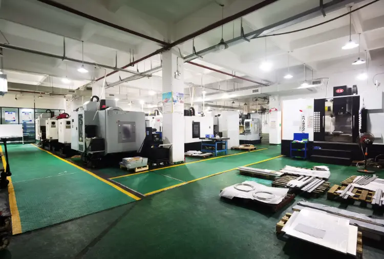
Outside diameter grinding, abbreviated as OD grinding, is also referred to as external cylindrical grinding. This process is used to finish the external cylindrical surfaces of arbres and other rotationally symmetrical parts.
Within a complete manufacturing route, Tournage CNC establishes basic features such as outside diameters, end faces, shoulders, grooves, and center holes. Heat treatment gives the part its specified hardness and mechanical properties. Outside diameter grinding then completes the final machining of bearing seats, sealing surfaces, sliding surfaces, and precision-fit diameters.
Outside diameter grinding controls more than diameter. The process must also control roundness, cylindricity, taper, runout, shoulder location, and surface integrity. The rotational datum, workholding rigidity, wheel condition, coolant delivery, thermal stability, and inspection method collectively determine the final quality.

What Is Outside Diameter Grinding?
Outside diameter grinding uses a high-speed grinding wheel to remove material precisely from the external cylindrical surface of a rotating workpiece. The wheel feeds radially into the part or travels axially along it until the outside diameter meets the size, geometric tolerance, and surface requirements on the drawing.
The abrasive grains on the wheel act as a large number of microscopic cutting edges. As they contact the workpiece, the grains pass through rubbing, plowing, and cutting and produce fine grinding swarf.
When the wheel becomes dull, loaded, or improperly dressed, the proportion of effective cutting decreases. Grinding force and contact-zone temperature then rise, causing chatter marks, grinding burn, dimensional drift, and surface-roughness deviations.
Outside diameter grinding locates the workpiece between centers, in a chuck, on a mandrel, or in a dedicated fixture. Shafts with several precision journals are ground between centers so that all journals share one rotational datum.
Centerless grinding also machines outside diameters, but it uses a different locating principle. Centerless grinding is suited to continuous batch production of pins, rollers, and round bar. Center-type outside diameter grinding is suited to complex shafts that require controlled coaxial relationships between journals, shoulder locations, and datum runout.
When Is Outside Diameter Grinding Required?
Adding a grinding operation increases manufacturing cost, so the process route must be based on part function and drawing requirements.
- Restoring dimensions after heat treatment: Hardening, carburizing, and nitriding produce dimensional change and form distortion. Outside diameter grinding restores journal size, roundness, cylindricity, and runout after heat treatment.
- Controlling tight geometric tolerances: When a drawing specifies diameter, roundness, cylindricity, or total runout together, outside diameter grinding performs the final finishing operation.
- Finishing sealing surfaces: Piston rods, pump shafts, and seal journals require a uniform surface texture with controlled directionality. Pronounced turning lead can produce an axial pumping effect and increase the risk of seal leakage.
- Finishing high-speed rotating components: Motor shafts, machine spindles, and rotor shafts are highly sensitive to bearing-seat runout. Journal error creates uneven bearing loading, vibration, noise, and localized heat.
- Keeping several journals coaxial: Gear shafts, transmission shafts, and stepped shafts contain several fitting diameters. Grinding critical diameters from a common datum controls the rotational relationship between bearing seats, gear seats, and sealing surfaces.
- Finishing coatings and repair layers: Hard-chromium plating, thermal spraying, and weld buildup on repaired shafts require outside diameter grinding to restore final size, profile, and surface quality.
Outside diameter grinding is not used to remove large volumes of material directly from a blank. The correct route is to establish the geometry by Tournage CNC, complete heat treatment, straightening, and datum restoration, and then grind the critical surfaces.
Main Outside Diameter Grinding Methods
Traverse Outside Diameter Grinding
In traverse grinding, the wheel moves back and forth along the workpiece axis while radial infeed progressively reduces the diameter.
- Suitable parts: Long shafts, piston rods, motor shafts, guide shafts, and cylindrical surfaces longer than the wheel width.
- Primary advantage: The method controls diameter, straightness, and cylindricity over a long effective surface.
- Commandes principales : Longitudinal feed, wheel overlap, reversal positions at both ends, and coolant coverage must remain stable. Excessive feed leaves pronounced spiral marks, while incorrect reversal positions create end-to-end size variation.
Plunge Outside Diameter Grinding
In plunge grinding, the wheel feeds radially into the workpiece. The wheel width covers the complete surface being ground.
- Suitable parts: Short journals, stepped diameters, bearing seats, and high-volume precision components.
- Primary advantage: The method shortens the cycle and forms the full journal width in one plunge.
- Commandes principales : A wide contact zone increases grinding force and thermal load. Machine rigidity, workpiece support, wheel sharpness, and coolant capacity must match the grinding width.
Form Outside Diameter Grinding
Form grinding uses a precisely dressed wheel profile to produce radii, tapers, grooves, and compound profiles.
- Suitable parts: Valve spools, formed journals, locating tapers, radius transitions, and precision tooling components.
- Primary advantage: The method forms several related dimensions in one plunge.
- Commandes principales : The final profile directly reproduces the working surface of the wheel. Dresser position, wheel profile, wheel wear, and CNC compensation must form a complete control chain.
Angular-Infeed Combination Grinding
Angular-infeed grinding uses the wheel periphery and side to grind an outside diameter and its adjacent shoulder in the same setup.
- Suitable parts: Bearing locating shoulders, flanged shafts, stepped shafts, and parts with tight face-runout requirements.
- Primary advantage: The method controls diameter, shoulder position, and face runout from one datum.
- Commandes principales : Wheel-side dressing, shoulder relief grooves, and fillet dimensions must meet the assembly requirements. The wheel side must not carry a grinding load beyond the process design.
Standard Outside Diameter Grinding Process
1. Review the Drawing and Functional Requirements
The material, heat-treatment condition, hardness, and blank condition must be confirmed before machining.
- Critical dimensions: Confirm final diameters, tolerances, journal lengths, shoulder locations, and fillet dimensions.
- Tolérances géométriques : Confirm roundness, cylindricity, straightness, coaxial requirements, circular runout, and total runout.
- Surface requirements: Confirm Ra, Rz, surface-texture direction, coating condition, and grinding-burn inspection requirements.
- Datum system: Confirm the measurement datum, machining datum, and assembly rotational axis.
- Grinding allowance: Confirm the stock left after turning and heat treatment and verify how evenly it is distributed.
2. Complete Pre-Machining and Heat Treatment
Usinage CNC or CNC turning first produces the outside diameters, end faces, shoulders, grooves, and center holes. Hardening, carburizing, nitriding, or another specified heat treatment is then completed in accordance with the material specification.
The grinding allowance must cover pre-machining error, oxide scale, and heat-treatment distortion. For carburized parts, the grinding allowance must also be coordinated with the effective case depth. The remaining hardened layer after grinding must satisfy the drawing and material specification; excessive grinding must not reduce the surface load-carrying capacity.
3. Check Straightness and Restore the Datum
Long shafts must be inspected for straightness after traitement thermique. Parts outside the process limit are straightened before precision grinding.
For grinding between centers, the center-hole angle, roundness, position, surface condition, and contact area must also be inspected. Burrs, impact damage, wear, or positional error in a center hole transfer directly to every ground journal.
An incorrect rotational datum cannot be corrected by changing the wheel infeed.
4. Inspect and Warm Up the Machine
Before precision grinding, inspect the wheel spindle, workhead, tailstock, guideways, lubrication system, guarding, and coolant system.
Warm up the machine in accordance with its operating specification so that the spindle, guideways, coolant, and measuring system reach a stable condition. If the thermal state is not stable, expansion of the machine structure and workpiece produces continuous dimensional drift.
5. Select and Mount the Grinding Wheel
The grinding wheel must be selected according to workpiece material, hardness, contact area, stock removal, surface-quality target, and available machine power.
Before mounting, inspect the wheel type, dimensions, appearance, and maximum operating speed. The actual wheel speed of the machine must not exceed the maximum permissible speed marked on the wheel.
The wheel must fit freely on the spindle and must never be forced into place. Flanges, blotters, and fastening methods must comply with the wheel manufacturer’s instructions. After installation, complete balancing, truing, dressing, and the prescribed unloaded trial run.
6. True and Dress the Grinding Wheel
Truing and dressing perform different functions.
- Truing: Restores wheel concentricity, cylindrical form, edges, and formed profiles.
- Dressing: Removes dull abrasive grains, bond material, and loading to re-establish an effective cutting surface.
Grinding stepped shafts, tapers, and radii also requires verification of the wheel’s actual profile. Batch production must define dressing depth, dressing speed, dresser position, and an initial dressing interval.
The final dressing interval is verified by dimensional trends, spindle power, surface quality, and wheel condition. A fixed part count is only the initial control method; process data determine the final dressing cycle.
7. Load and Align the Workpiece
The workholding method must match the functional datum.
- Between-center mounting: Used for precision shafts in which several journals share one rotational datum.
- Chuck mounting: Used for short shafts, parts without center holes, and components located from an end face or outside diameter.
- Mandrel mounting: Used for sleeves and ring-shaped parts whose precision bore is the rotational datum.
- Dedicated fixturing: Used for thin-walled parts, irregular components, and batch parts that require repeatable location.
Slender shafts use a steady rest, following support, or dedicated support device to control deflection. Insufficient support force allows vibration; excessive force shifts the natural workpiece axis and creates unloaded form error.
8. Trial Grind and Rough Grind
Before full machining, make a light trial grind to confirm workpiece rotation, wheel-contact position, coolant coverage, and coordinate compensation.
Rough grinding removes the main stock. Use staged infeeds rather than replacing several stable passes with one heavy cut. During the cycle, monitor sparks, sound, vibration, spindle load, coolant condition, and workpiece temperature.
9. Semi-Finish and Finish Grind
Semi-finishing corrects taper, roundness, and local high spots left by rough grinding and establishes a uniform finish-grinding allowance.
Reduce radial infeed as the workpiece approaches final size. Finish grinding targets geometric accuracy, surface quality, and thermal stability; it must not carry a large stock-removal load.
10. Complete Spark-Out
During spark-out, radial infeed stops while the wheel completes the specified grinding cycles.
Spark-out releases elastic deflection in the machine, fixture, and workpiece system and improves dimensional repeatability, roundness, and surface roughness.
Spark-out cannot correct an incorrect datum, pronounced taper, severe bending, or unstable workpiece support.
11. Perform Final Inspection and Protect the Finished Part
Inspection is performed after the workpiece, measuring instrument, and measurement environment reach thermal equilibrium.
- Dimensional inspection: Check outside diameters, lengths, shoulder locations, and fitting dimensions.
- Form inspection: Check roundness, cylindricity, taper, and straightness.
- Positional inspection: Check circular runout, total runout, and rotational relationships between journals from the drawing datums.
- Surface inspection: Check roughness, texture direction, scratches, chatter, grinding burn, and cracks.
- Record control: Retain first-piece, in-process, and final-inspection results.
After cleaning, precision-ground surfaces receive rust protection and separated packaging to prevent impact damage, corrosion, and contamination during transportation.

What Must Be Controlled During Outside Diameter Grinding?
Keep the Grinding Allowance Uniform
Excessive grinding stock increases machining time, wheel consumption, grinding force, and heat. Insufficient stock prevents the complete removal of turning marks, oxide scale, and heat-treatment distortion.
The allowance must also remain uniform around the circumference and along the axis. Eccentric or bent workpieces subject the wheel to cyclic load variation, which produces vibration, localized burn, and form error.
Heat-treatment distortion, center-hole damage, and datum shift must be corrected before finish grinding.
Use a Consistent Rotational Datum
Turning and grinding must use a continuous datum system. After heat treatment, inspect and restore the center holes so that the physical datum remains stable.
When runout is specified between several journals, grind the critical diameters in one setup or from a verified common datum. Repeated changes of locating surface introduce datum-transfer error.
Individual journal diameters can meet size requirements while total runout between the journals remains out of tolerance.
Select the Grinding Wheel Correctly
Grinding-wheel selection cannot be based only on abrasive type.
- Abrasive: Determines the wheel’s cutting compatibility with the workpiece material.
- Grit size: Coarse grit improves chip clearance and stock removal; fine grit is used for smaller finishing allowances and lower roughness.
- Wheel grade: Describes the bond’s ability to retain abrasive grains, not the hardness of the grains themselves.
- Structure : An open structure improves chip clearance and coolant access; a dense structure increases the number of grains per unit area.
- Bond: Determines wheel strength, elasticity, speed capability, and dressing method.
- Contact area: As the contact area increases, the demands on chip clearance and heat dissipation also increase.
Workpiece material, grinding method, surface requirement, wheel speed, coolant method, and spindle power must all be included in wheel selection.
Maintain a Stable Dressed Condition
During grinding, the wheel continuously becomes dull, loaded, and geometrically worn. Dressing intervals cannot depend entirely on an operator’s subjective judgment.
Dressing depth, dressing speed, dresser position, and dressing interval must form a process standard. Batch production must also monitor spindle power, dimensional trends, and changes in surface roughness.
Insufficient dressing increases grinding force, rubbing, and burn risk. Excessive dressing increases wheel consumption and changes the wheel surface too rapidly.
Control Coolant Delivery and Thermal Distortion
Grinding fluid must enter the actual wheel-workpiece contact arc continuously. Fluid that merely wets the outside of the workpiece does not provide effective coolant delivery to the grinding zone.
- Nozzle position: The fluid stream must enter the contact zone without significant deflection from the high-speed air barrier around the wheel.
- Coolant flow: Flow must satisfy cooling, lubrication, chip-removal, and wheel-cleaning requirements.
- Filtration condition: The filtration system must continuously remove abrasive particles, metal swarf, and coating debris.
- Concentration control: Water-based grinding-fluid concentration must be measured and replenished in accordance with the supplier’s technical requirements.
- Temperature control: The coolant, workpiece, and measuring instruments must maintain a stable temperature relationship.
Swarf re-entering the grinding zone causes random scratches, wheel loading, and roughness variation. Temperature changes create dimensional drift and interfere with compensation decisions.
Approach Final Size in Stages
Rough grinding, semi-finishing, finish grinding, and spark-out must have a defined stock distribution.
Finish grinding must not continue to remove a large amount of material. Excess finishing stock raises grinding heat, increases dimensional springback, and reduces surface-quality stability.
Semi-finishing first corrects form, and finish grinding then completes size and surface requirements. This is the basic route to a stable result.
Protect Shoulders, Fillets, and Relief Grooves
The wheel edge must match the shoulder, fillet, and relief-groove geometry.
An undersized fillet increases stress concentration. An oversized fillet interferes with a bearing, gear, or sleeve. Inadequate relief also places an additional load on the wheel side, causing shoulder burn and positional error.
Control the Texture of Sealing Surfaces
Ra alone is not sufficient for evaluating a seal journal.
Rotary sealing surfaces also require control of Rz, Rt, peak-and-valley structure, and surface-texture direction. A pronounced helical lead generates an axial pumping action on the sealed fluid.
When the sealing specification requires a lead-free surface or defines surface-lead limits, the specified inspection method must verify compliance; visual judgment of apparent smoothness is not sufficient.

Key Outside Diameter Grinding Parameters
Grinding parameters interact with one another. Every parameter must be set together with the wheel specification, material condition, contact width, and workholding rigidity.
- Wheel surface speed: Determines how quickly abrasive grains pass through the contact zone. The actual operating speed must not exceed the maximum permitted by the wheel and the machine.
- Workpiece speed: Influences undeformed chip thickness, grinding force, surface texture, and productivity.
- Radial infeed: Determines stock removed during each pass. Increasing infeed raises grinding force, spindle load, and heat input at the same time.
- Longitudinal feed: Determines the wheel’s axial travel rate. Longitudinal feed and wheel width together determine overlap and spiral-mark condition.
- Dressing parameters: Dressing depth and speed alter wheel sharpness, surface topography, and final roughness.
- Spark-out cycle: The specified spark-out cycle releases elastic deflection. Excessive spark-out reduces efficiency and increases non-cutting friction.
Change only one major variable at a time during process optimization, and record dimensions, spindle power, roughness, temperature rise, and wheel condition. Changing several parameters simultaneously destroys the relationship required for root-cause tracing.
What Accuracy Characteristics Must Outside Diameter Grinding Control?
Diameter tolerance limits size only; it does not fully describe the form and rotational condition of a cylindrical surface.
- Diameter tolerance: Determines the fit between the shaft and a bearing, seal, sleeve, or gear.
- Roundness: Limits form error within a single cross-section.
- Cylindricity: Controls the combined form error of the entire effective cylindrical surface without reference to an external datum.
- Straightness: Limits bending of a cylindrical generating line or derived axis.
- Circular runout: Checks the variation of a specified cross-section during one revolution relative to a datum axis.
- Total runout: Checks the combined variation of the entire surface relative to a datum axis.
- Taper: Controls the end-to-end diameter difference, taper angle, and effective contact condition.
- Rugosité de surface : Affects friction, lubrication, sealing, wear, and fatigue life.
Precision outside diameter grinding controls size and form in micrometers. Actual deliverable capability is determined by workpiece diameter, effective length, length-to-diameter ratio, material hardness, workholding method, thermal stability, and the measurement system.
A machine’s rated accuracy is not the same as the batch capability of a specific part. The supplier must demonstrate manufacturing capability through first-piece and in-process data.
How Is Outside Diameter Grinding Quality Inspected?
Diameter Inspection
An outside micrometer measures local diameter; it does not replace form and positional-tolerance inspection.
Long shafts must be measured at both ends, at the center, and at the locations specified on the drawing. Each location must also be measured in different circumferential directions to identify taper, ovality, and local size variation.
Roundness Inspection
Roundness must be measured with a roundness tester or a validated rotational measurement system. The result must identify the measured cross-section, filter conditions, evaluation method, and equipment used.
Two-point micrometer measurement cannot fully identify lobing or high-frequency waviness.
Cylindricity Inspection
Cylindricity inspection requires data from multiple circumferential sections and axial generating lines, followed by evaluation of the complete surface with a cylindricity measuring system or a coordinate measuring system that meets the requirement.
Measuring only the diameter difference between the two ends indicates a taper trend; it does not prove cylindricity compliance.
Runout Inspection
Circular runout and total runout must be measured relative to the datum axis specified on the drawing. The measurement setup must reproduce the datum system and must not use arbitrary support locations.
For parts with several journals, inspection must focus on the relative runout between bearing seats, gear seats, and sealing surfaces.
Surface-Integrity Inspection
The absence of visible discoloration does not prove that a part is free from grinding thermal damage.
- Grinding burn: For hardened ferromagnetic steel parts, use nital etching, Barkhausen-noise inspection, or another validated dedicated method.
- Hardness change: Perform surface or microhardness testing at the specified locations.
- Surface cracks: Use magnetic-particle inspection for ferromagnetic materials and penetrant inspection for surface-breaking cracks in nonporous materials.
- Roughness and texture: Use a profilometer to measure the specified parameters in the direction required by the drawing.
The inspection method must match the material, heat-treatment condition, and failure risk of the part.
Common Outside Diameter Grinding Problems and Solutions
Roundness Out of Tolerance
Roundness problems begin with the rotational datum, wheel condition, and workpiece support.
- Primary causes: Burrs or wear in the center holes, misalignment between the workhead and tailstock, wheel imbalance, unstable workpiece support, or abnormal spindle condition.
- Troubleshooting sequence: Inspect the center holes and locating contact first, then check wheel balance and dressing condition. Confirm the steady-rest position next, and only then adjust finish infeed and spark-out parameters.
Reducing infeed only lowers grinding force; it does not correct roundness error caused by an incorrect datum.
Taper on the Workpiece
- Primary causes: Nonparallel workhead and tailstock axes, incorrect table angle, localized wheel wear, uneven coolant distribution, or inconsistent support conditions.
- Corrective action: Align the machine axes with a test bar, check the table angle, true and dress the wheel again, and provide uniform coolant coverage over the complete grinding length.
Measure both ends and the center of a long shaft to distinguish machine-alignment error from workpiece bending.
Chatter Marks on the Surface
- Primary causes: Poor wheel balance, resonance excited by workpiece speed, inadequate fixture rigidity, incorrect steady-rest setting, spindle vibration, or vibration transmitted from surrounding equipment.
- Corrective action: Check wheel balance, workholding, and support first, and then adjust workpiece speed, feed, and wheel specification one step at a time.
Speed changes must be verified against the resulting vibration. Simply reducing speed is not a fixed solution because the new speed can enter another resonance range.
Grinding Burn or Discoloration
- Primary causes: Excessive infeed per pass, a dull or loaded wheel, an unsuitable wheel grade, inadequate coolant coverage, or excessive finishing stock.
- Corrective action: Dress the wheel, reduce the finishing thermal load, improve coolant coverage, and redistribute stock between roughing and finishing.
A burned part cannot be accepted merely because polishing removes the color. Critical parts also require verification of hardness change, residual stress, and surface cracking.
Surface Roughness Out of Tolerance
- Primary causes: Unsuitable wheel grit or grade, unstable dressing conditions, excessive finishing infeed, insufficient spark-out, or grinding swarf in the coolant.
- Corrective action: Reconfirm the full wheel specification, standardize the dressing parameters, reduce final infeed, and restore coolant filtration.
A roughness problem cannot be solved only by installing a finer-grit wheel. Wheel dulling and machine vibration still damage the final surface.
Continuous Dimensional Drift
- Primary causes: Unstable machine, workpiece, and coolant temperatures; continuous wheel wear; incorrect compensation rules; changing measurement conditions; or an uncontrolled dressing cycle.
- Corrective action: Complete the machine warm-up, standardize temperature and measurement methods, and establish dressing, measurement, and dimensional-compensation rules from process data.
Slender-Shaft Bending
- Primary causes: Excessive tailstock force, incorrect support position, excessive local grinding force, release of residual stress, or uneven cooling.
- Corrective action: Check straightness before grinding, adjust tailstock and support force, reduce localized infeed, and position the support near the main grinding zone.
A clearly bent blank must be straightened before grinding; grinding cannot be used to force it into alignment.
Wheel Loading
- Primary causes: Adhesion of a ductile material, an overly dense wheel structure, a wheel grade that is too hard, insufficient dressing, or failed coolant filtration.
- Corrective action: Use a wheel with an open structure and suitable self-sharpening behavior, adjust the dressing cycle, and restore coolant cleanliness.
Spiral or Traverse Marks
- Primary causes: Excessive longitudinal feed, incorrect dressing of the wheel edge, an incorrect relationship between the wheel axis and table travel, or insufficient overlap.
- Corrective action: Correct the wheel-to-table relationship, redress the wheel edge, and reset longitudinal feed according to wheel width.
Norton’s cylindrical-grinding troubleshooting material likewise identifies center-hole condition, support, wheel balance, coolant delivery, and dressing as primary inspection points.

Common Materials and Grinding-Wheel Selection
- Carbon and alloy steels: Used for transmission shafts, gear shafts, and hydraulic rods. Aluminum-oxide wheels are suited to conventional roughing and finishing.
- Bearing steels and hardened steels: Used for bearing seats, rollers, and precision journals. Aluminum-oxide wheels suit conventional production, while CBN wheels suit high-hardness parts and stable batch production.
- Tool steels: Used for guide posts, punches, and precision arbors. The wheel must maintain stable self-sharpening behavior, and grinding heat must be controlled strictly.
- Stainless steels: Material ductility increases the risk of wheel loading. The wheel must remain sharp and operate with effective coolant delivery and stable dressing.
- Cast iron: Used for sleeves, machine components, and large rolls. Silicon-carbide wheels are suited to many cast-iron outside diameter grinding operations.
- Titanium and nickel-based alloys: Heat concentrates in the grinding zone and wheel wear accelerates. The process must increase wheel sharpness, chip-clearance capacity, and cooling efficiency.
- Cemented carbides and ceramics: Diamond wheels are used with low-impact infeed to control edge chipping and surface damage.
- Chrome-plated and thermally sprayed surfaces: The wheel must match the coating type, thickness, porosity, and bond strength to prevent cracking and delamination.
Diamond wheels are not used for conventional grinding of ordinary steels. Grinding heat accelerates chemical wear between diamond and ferrous materials and shortens wheel life.
Typical Outside Diameter Grinding Applications
- Automotive and electric-drive components: Motor shafts, transmission shafts, gear shafts, steering shafts, shock-absorber piston rods, and crankshaft journals.
- Hydraulic and fluid-control components: Piston rods, plungers, pump shafts, and valve spools that require stable sealing diameters and surface textures.
- Bearings and high-speed rotating components: Bearing seats, machine spindles, and rotor shafts that require controlled roundness and relative runout.
- Molds and precision tooling: Guide posts, arbors, gauges, and mold fitting diameters that require stable dimensional repeatability.
- Industrial rolls: Printing rolls, coating rolls, conveyor rolls, and mill rolls that require control of full-length straightness, cylindricity, runout, and compensated profiles.
Operator Safety During Outside Diameter Grinding
Outside diameter grinding involves a high-speed wheel and a rotating workpiece. Only personnel trained in the machine, grinding wheel, and safeguarding requirements may operate the equipment.
- Wheel inspection: Before mounting, inspect the wheel type, dimensions, damage, and maximum operating speed. A ring test applies only to wheel types for which the wheel manufacturer and safety standard require it; the response of resin and other organic-bonded wheels must not be judged in the same way as that of vitrified wheels.
- Mounting inspection: Use the specified flanges, blotters, and fastening method. Never force a wheel onto the spindle or overtighten the nut to eliminate clearance.
- Machine guarding: Confirm that the wheel guard, machine-door lock, and safety interlocks function correctly. No person may remove, disable, or bypass a safety device.
- Workpiece mounting: Confirm that the chuck, centers, tailstock, and steady rest are locked. Remove tools, measuring instruments, and adjustment bars from the working area before startup.
- Unloaded trial run: Complete the wheel manufacturer’s specified unloaded trial run after installing a new wheel. Keep the guard door closed and remain outside the plane of wheel rotation.
- Personal protection: Wear safety glasses and safety footwear, and use a face shield and hearing protection in accordance with the workplace risk assessment. Keep work clothing close-fitting, fully secure long hair, and remove jewelry from the work area.
- Rotating zone: Do not touch, measure, clear swarf, or adjust the steady rest while the wheel or workpiece is rotating. Keep gloves away from rotating components.
- Abnormal-condition shutdown: Stop the machine immediately if abnormal vibration, interrupted coolant flow, a loose workpiece, unusual noise, or abnormal temperature rise occurs. Resume machining only after identifying and correcting the cause.
- Energy isolation: Before changing a wheel, adjusting a guard, clearing entangled swarf, or servicing the machine, wait for the equipment to stop completely and apply energy-isolation procedures.
OSHA 29 CFR 1910.215 requires effective guarding on abrasive-wheel machinery and inspection of wheel damage, mounting condition, and maximum operating speed before installation.
How Does Weldo Maintain Outside Diameter Grinding Stability?
Weldo does not use a machine’s rated accuracy alone to determine project capability. Engineering review combines material, hardness, diameter, effective grinding length, length-to-diameter ratio, workholding method, heat-treatment condition, and inspection method to establish the manufacturing plan.
Drawing and Process Review
- Identify functional surfaces: Define bearing seats, sealing surfaces, gear mounting locations, and other critical fitting diameters.
- Confirm datum relationships: Confirm machining datums, measurement datums, assembly axes, and runout requirements between multiple journals.
- Plan the manufacturing route: Sequence CNC turning, heat treatment, straightening, center-hole restoration, outside diameter grinding, and surface treatment correctly.
- Review the grinding allowance: Confirm that the stock removes upstream error while retaining the specified hardened case or coating thickness.
Trial Production and First-Article Validation
Trial production validates the workholding method, wheel specification, dressing method, coolant conditions, infeed distribution, and dimensional-compensation method.
First-article inspection covers more than diameter. Roundness, cylindricity, runout, shoulder location, roughness, and surface integrity specified on the drawing are included in validation.
When a deviation appears, the datum, workholding, support, and wheel condition are analyzed before infeed or compensation is changed. This sequence prevents dimensional compensation from hiding the true process problem.
Batch Process Control
- Wheel management: Record wheel specification, dressing parameters, dressing cycle, and replacement criteria.
- In-process measurement: Define first-piece, patrol-inspection, and final-inspection frequency and monitor dimensional trends.
- Temperature control: Standardize machining, coolant, and measurement conditions to reduce thermal drift.
- Compensation control: Apply dimensional compensation from measured trends and prohibit undocumented temporary adjustments.
- Data traceability: Retain critical process parameters, measurement data, and nonconformance actions.
- Finished-part protection: Clean, protect against corrosion, separate, and impact-protect precision-ground surfaces.
What Factors Affect Outside Diameter Grinding Cost?
Outside diameter grinding cost is determined by machining time, workholding difficulty, wheel consumption, and inspection depth.
- Part size and length-to-diameter ratio: Long and slender shafts require greater machine travel, auxiliary support, straightening, and additional straightness inspection.
- Number and structure of journals: Multiple shoulders, journals, fillets, and tapers increase dressing, programming, and measurement time.
- Material and hardness: Hardened steel, cemented carbide, titanium alloys, and coated parts require dedicated wheel specifications and process parameters.
- Blank condition: Bending, eccentricity, excessive stock, and uneven allowance increase straightening, rough-grinding, and in-process inspection time.
- Tolérances géométriques : Tight roundness, cylindricity, and total-runout requirements raise the demands on the datum, thermal control, machine condition, and inspection equipment.
- Surface requirements: Low roughness, lead-free sealing surfaces, and specified profile parameters increase dressing and inspection work.
- Surface integrity: Grinding-burn, hardness, and crack inspections add quality-verification cost.
- Quantité achetée : Low-volume cost is concentrated in process preparation, workholding, and first-article validation; production cost is concentrated in wheel management, compensation, and process control.
- Delivery condition: Heat treatment, coating, polishing, corrosion protection, inspection documents, and dedicated packaging affect the complete quotation.
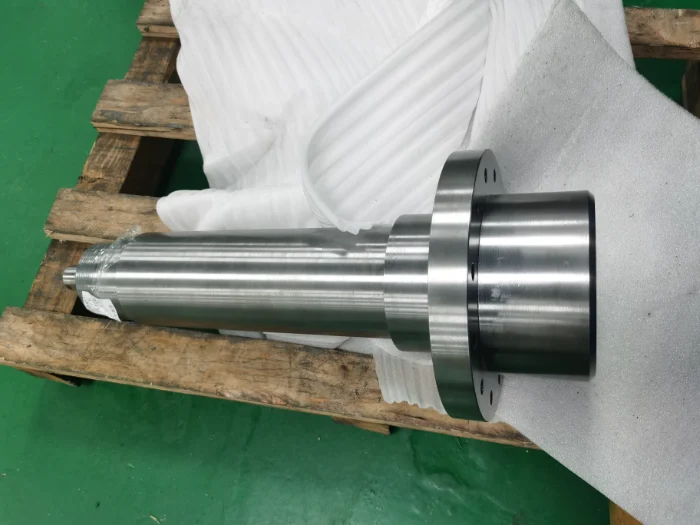
What Information Is Required for an Outside Diameter Grinding RFQ?
A complete RFQ needs only the information that affects process decisions.
- Engineering drawing: Provide a 2D drawing with dimensions, datums, and geometric tolerances.
- Material condition: Provide the material grade, heat-treatment method, and final hardness.
- Blank information: Provide the pre-grinding diameter, grinding allowance, straightness, and surface condition.
- Critical requirements: Identify roundness, cylindricity, runout, roughness, and functional surfaces.
- Purchasing information: Provide prototype quantity, production quantity, and required delivery date.
- Quality documents: Define full-dimensional reports, material certificates, hardness reports, and special inspection requirements.
Conclusion
Outside diameter grinding does more than reduce a part’s diameter. It is a precision manufacturing process that controls the rotational datum, size, geometric form, surface texture, and surface integrity at the same time.
A stable outside diameter grinding process begins with drawing review and pre-machining. A suitable grinding allowance, controlled heat treatment, sound center holes, and a correct workholding plan determine whether the part has a reliable foundation for finish grinding.
During grinding, wheel selection, truing and dressing, coolant delivery, staged infeed, and standardized inspection collectively determine batch consistency.
For custom motor shafts, gear shafts, piston rods, pump shafts, valve spools, precision journals, or coated repair components, send Weldo the drawing, material, hardness, quantity, and critical tolerances. The engineering team will complete a manufacturability review and provide a clear process plan and quotation.