
Een waterverdeelstuk is meer dan alleen een connector met meerdere aansluitingen. Het heeft een directe invloed op de doorstroming in de aftakkingen, de drukval in het systeem, het pompvermogen, de afdichting van de aansluitingen en het onderhoud van de apparatuur.
Inzicht hoe kies je een waterverdeelstuk? begint met het vaststellen van de bedrijfsomstandigheden – en niet alleen met het tellen van het aantal poorten. Ingenieurs moeten het drukverliesbudget van het systeem vaststellen, de weerstand in de hoofdleiding en de aftakkingen berekenen en functionele eisen omzetten in meetbare acceptatiecriteria.
In deze handleiding wordt uitgelegd hoe u een specificatie voor een waterverdeelstuk kunt opstellen die kan worden berekend, vervaardigd en gecontroleerd.
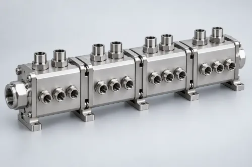
1. Bepaal de volledige ontwerpvoorwaarden aan de waterzijde
Een leverancier kan een onderdeel wellicht volgens de tekening vervaardigen. Het feit dat de afmetingen kloppen, is echter op zich geen garantie dat het verdeelstuk aan de vereiste systeemprestaties zal voldoen.
De volgende informatie moet worden vastgelegd voordat met het ontwerp wordt begonnen.
| Ontwerpinputs | Vereiste informatie | Wat het beïnvloedt |
|---|---|---|
| Werkvloeistof | Soort, concentratie, pH, geleidbaarheid en additieven | Materiaal, afdichtingen en reinigingsmethode |
| Totale doorstroomhoeveelheid | Maximale gelijktijdige bedrijfsstroom | Hoofdleiding en aansluiting op de toevoerleiding |
| Doorstroomsnelheid in de vertakking | Streefdebiet voor elke uitlaat | Diameter van de vertakking en ontwerp voor stromingsbalans |
| Werkdruk | Normale systeemdruk | Aansluitingen en afdichtingen |
| Ontwerpdruk | Maximale druk waarmee bij het ontwerp van het systeem rekening is gehouden | Materiaal, wanddikte en structuur |
| Toegestane drukval | Drukverlies toegerekend aan het verdeelstuk | Afmetingen en indeling van de passage |
| Bedrijfstemperatuur | Minimum-, normale en maximumtemperaturen | Viscositeit van vloeistoffen en materiaalprestaties |
| Bedrijfsmodi | Vollast, deellast en stand-by-toestand | Stromingsverdeling en regelingsstrategie |
Maak onderscheid tussen vier drukklassen
Werkdruk is de druk die tijdens normaal bedrijf van het systeem heerst.
Ontwerpdruk wordt gebruikt om de materiaalkeuze, het constructieontwerp en de veiligheidsmarges te bepalen. Hierbij moet rekening worden gehouden met de hoogste druk waaraan het onderdeel onder vastgestelde omstandigheden kan worden blootgesteld.
Testdruk wordt gebruikt om de integriteit van het product te controleren. Dit moet worden vastgelegd in de ontwerpvereisten, de toepasselijke norm of de technische overeenkomst.
Barstdruk wordt gebruikt om de uiteindelijke breukgrens te bepalen. Het is geen vervanging voor routinematige productiedrukproeven.
Er mag niet voor elk waterverdeelstuk een vaste testdrukvermenigvuldigingsfactor worden toegepast. De verantwoordelijke projectingenieur moet de juiste waarde voor het specifieke systeem vaststellen.
Beoordeel omstandigheden buiten het ontwerpbereik
Bij een volledige ontwerpbeoordeling moet ook rekening worden gehouden met:
- Sommige vestigingen zijn gesloten
- Schommelingen in het pomptoerental
- Verhoogde filterweerstand
- Opstarten van het koelsysteem bij lage temperatuur
- Onvolledige ontluchting van het systeem
- Snelle klepwerking
- Toekomstige uitbreiding van de apparatuur
Deze omstandigheden kunnen de doorstroming in de aftakking, de systeemdruk en het werkelijke werkpunt van de pomp beïnvloeden.
2. Bepaal de afmetingen van de doorgangen op basis van de drukvalbalans van het systeem
De schroefdraadmaat van de aansluiting geeft niet rechtstreeks de doorstroomcapaciteit van een verdeelstuk weer. De werkelijke capaciteit hangt af van de effectieve doorstroomdoorsnede, de doorstroomlengte en de lokale stromingsweerstand.
2.1 Bereken het totale debiet
Voor een stabiele, niet-samenpersbare vloeistof:
Qtotaal = Q1 + Q2 + Q3 + … + Qn
Als er bijvoorbeeld acht koelvertakkingen tegelijkertijd in bedrijf zijn en elk daarvan 2 l/min nodig heeft, moet de hoofdleiding een totale ontwerpstroom van 16 l/min aankunnen.
Als de takken niet gelijktijdig in bedrijf zijn, moet het totale debiet worden berekend op basis van de besturingslogica en de maximaal verwachte gelijktijdige vraag. Het simpelweg optellen van alle nominale debieten van de takken kan leiden tot een te groot gedimensioneerd ontwerp.
2.2 Bepaal de benodigde doorgangsoppervlakte
Het debiet, de doorsnede en de gemiddelde snelheid staan met elkaar in verband via:
Q = A × V
Waar:
- Q is het volumestroom
- A is de effectieve doorstromingsdoorsnede
- V is de gemiddelde stroomsnelheid
Deze verhouding vormt een eerste uitgangspunt voor het bepalen van de afmetingen van de hoofd- en zijkanalen.
Te smalle doorgangen zorgen voor een hogere vloeistofsnelheid en een grotere drukval. Onnodig grote doorgangen leiden tot grotere afmetingen, een hoger gewicht en hogere productiekosten van het onderdeel.
2.3 Berekening van wrijvings- en lokale drukverliezen
Voor niet-samendrukbare vloeistoffen op waterbasis kan de Darcy–Weisbach-vergelijking worden gebruikt voor technische schattingen:
Δp = [f(L/Dh) + ΣK] × ρV²/2
Waar:
- f is de wrijvingscoëfficiënt
- L is de lengte van de doorgang
- Dh is de hydraulische diameter
- ρ is de dichtheid van de vloeistof
- V is de gemiddelde stroomsnelheid
- K is de lokale verliescoëfficiënt
Lokale verliezen binnen een waterverdeelstuk mag niet worden genegeerd. Veelvoorkomende bronnen zijn onder meer:
- Kruisende geboorde gangen
- Plotselinge afname van de grootte van de doorgang
- Scherpe bochten
- Haveningangen
- Snelkoppelingen
- Kleppen
- Beperkingsopeningen
- Stroomrichtingsveranderingen in de buurt van doorgangpluggen
Koelvloeistoffen op basis van glycol worden bij lage temperaturen stroperiger. Bij berekeningen van drukverlies moet daarom rekening worden gehouden met de eigenschappen van de vloeistof bij de opgegeven concentratie en bedrijfstemperatuur.
2.4 Een volledig drukverliesoverzicht voor het systeem opstellen
Het beschikbare pompdrukverschil moet de weerstand van de volgende factoren overwinnen:
- Koelplaten
- Filters
- Slangen
- Snelkoppelingen
- Regelkleppen
- Warmtewisselaars
- Toevoerverdeelstukken
- Retourverdeelstukken
Voordat het toegestane drukverlies aan het verdeelstuk wordt toegewezen, moet de volledige drukverliesberekening voor het circuit worden opgesteld.
Een pomp kan bijvoorbeeld bij het beoogde debiet een drukverschil van 120 kPa leveren. Als koelplaten, filters, slangen, koppelingen en de vereiste ontwerpmarge al 110 kPa in beslag nemen, kunnen de gecombineerde aanvoer- en retourverdeelstukken slechts gebruikmaken van de resterende 10 kPa.
Zelfs als het verdeelstuk een debiet van 16 l/min aankan, is het ontwerp ongeschikt als de drukval groter is dan de beschikbare 10 kPa.
3. Ontwerp van de stroming rond de thermische belasting
Aansluitingen met dezelfde diameter leveren niet noodzakelijkerwijs hetzelfde debiet. Het werkelijke debiet in de aftakking hangt af van het drukverschil over de aftakking en de totale hydraulische weerstand ervan.
3.1 Waarom varieert de stroming in de vertakkingen?
Veelvoorkomende oorzaken zijn onder meer:
- Drukveranderingen langs de hoofddoorgang
- Verschillende taklengtes
- Verschillende aantallen bochten
- Variaties in de diameter van de snelkoppeling
- Verschillende stromingsweerstanden van koelplaten
- Asymmetrische opstellingen van aanvoer- en retourleidingen
- Verschillende tegendrukken aan de uitlaatzijde
- Niet goed uitgelijnde, elkaar kruisende doorgangen of achtergebleven bramen
Identieke takdiameters mogen niet worden beschouwd als bewijs van een evenwichtige stroming.
3.2 Bepaal of een gelijke doorstroming daadwerkelijk vereist is
Als alle koelplaten dezelfde thermische belasting en interne weerstand hebben, kan een gelijke stroming in de vertakkingen een geschikt ontwerpdoel zijn.
Als de thermische belastingen verschillen, moet elke tak worden gedimensioneerd op basis van zijn eigen koelbehoefte. Apparatuur met een hogere belasting heeft mogelijk meer koelvloeistof nodig, terwijl apparatuur met een lagere belasting mogelijk minder nodig heeft.
Een geschikter ontwerpdoel is:
Stem het werkelijke debiet in de afzakkingen af op de benodigde warmtebelasting, in plaats van elke afzakkingen te dwingen hetzelfde debiet te leveren.
3.3 Gangbare methoden voor het in evenwicht brengen van stromen
- Pas de doorsnede van de hoofdgang aan
- Gebruik symmetrische of op weerstand gelijkwaardige doorgangsindelingen
- De richtingen van de aanvoer- en retourstromen optimaliseren
- Hydraulische lengte van de stuurarm regelen
- Verminder plotselinge uitzettingen en scherpe bochten
- Pas de effectieve takdiameter aan
- Voeg gekalibreerde restrictoropeningen toe
- Installeer balanceringskleppen of stroomregelaars
Beperkingsopeningen kunnen de stromingsverdeling verbeteren, maar zorgen ook voor een groter drukverlies. Bij het ontwerp moet een evenwicht worden gevonden tussen de gelijkmatigheid van de stroming en het pompvermogen.
3.4 CFD correct gebruiken
Computational Fluid Dynamics is nuttig wanneer een verdeelstuk veel aftakkingen heeft, een asymmetrische opbouw heeft of aan strenge eisen op het gebied van stromingsverdeling moet voldoen.
Het model moet het volgende bevatten:
- Werkelijke eigenschappen van het koelmiddel
- Bedrijfstemperatuur
- Toevoerstroom of -druk
- Weerstand van de koelplaat
- Weerstand van slangen en koppelingen
- Realistische tegendruk aan de uitlaat
- Bedrijfsomstandigheden waarbij sommige vestigingen gesloten zijn
CFD helpt bij het vergelijken van ontwerpvarianten en het opsporen van lokale stromingsrisico’s. De uiteindelijke stromingsverdeling moet nog steeds worden geverifieerd door middel van fysieke tests.
4. Selecteer poorten als functionele vloeistofcomponenten
Een poort is niet louter een mechanische verbinding. Het is tevens een concentratie van lokale stromingsweerstand, risico’s op lekkage en onderhoudsvereisten.
4.1 De norm voor aansluitingen en afdichtingen vaststellen
In de tekening moet het volgende worden aangegeven:
- NPT, BSPT, BSPP, SAE ORB of metrische schroefdraad
- Nominale maat en schroefdraadspoed
- Effectieve draaddiepte
- Afdichtingsmethode
- Oriëntatie van de poort
- Geschikt model of specificatie
- Aanhaalmoment
BSPP- en SAE ORB-aansluitingen maken doorgaans gebruik van een afdichtingsring of een O-ring. NPT- en BSPT-aansluitingen maken gebruik van conische schroefdraden in combinatie met de voorgeschreven afdichtingsmethode.
Deze interfacenormen zijn niet onderling uitwisselbaar.
4.2 Vergelijk de werkelijke doorstroomcapaciteit
Fittingen met dezelfde nominale maat kunnen verschillende minimale binnendiameters en doorstroomcoëfficiënten hebben.
Controleer bij snelkoppelingen ook het volgende:
- Minimale doorstromingsdiameter
- Stroomcoëfficiënt
- Drukval bij het opgegeven debiet
- Of er een interne afsluitklep is gemonteerd
- Verlies van resterende vloeistof tijdens het loskoppelen
- Toegestaan aantal schakelcycli
- Materiaal van de afdichting
- Werkdruk en temperatuur
Voor dat doel mogen uitsluitend snelkoppelingen worden gebruikt die specifiek zijn ontworpen voor het aansluiten of loskoppelen onder druk.
4.3 Het aantal adapterkoppelingen tot een minimum beperken
Elke extra adapter voegt normaal gesproken het volgende toe:
- Nog een afdichtingsinterface
- Een ander mogelijk lekpunt
- Extra lokaal drukverlies
- Grotere installatielengte
- Extra montagetijd
- Nog een onderhoudspunt
Wanneer het bijpassende onderdeel al bekend is, moet de benodigde aansluiting, voor zover praktisch haalbaar, rechtstreeks in het verdeelstuk worden gefreesd.
4.4 Controleer de inbouwruimte aan de hand van het complete assemblagemodel
Een botsingsvrije inrichting van de aansluitingen betekent niet noodzakelijkerwijs dat het verdeelstuk ter plaatse kan worden geïnstalleerd of onderhouden.
De evaluatie van de vergadering moet het volgende omvatten:
- Maximale inbouwdiameter
- Speling van de moersleutel
- Snelkoppeling: bewegingsweg bij koppelen en ontkoppelen
- Minimale buigradius van de slang
- Afmetingen van de sensor
- Richting van de kabeluitgang
- Vrije ruimte voor ontluchting en afvoer
- Traject voor het verwijderen van onderdelen
5. Bekijk het volledige systeem van met vloeistof in contact komende materialen
Corrosie is geen vaststaand kenmerk van één bepaald materiaal. Het is het gevolg van de wisselwerking tussen de materiaalcombinatie, de samenstelling van het koelmiddel, de temperatuur en de bedrijfsomgeving.
5.1 Een volledige lijst van materialen die in contact komen met vloeistoffen opstellen
De lijst moet het volgende bevatten:
- Verdeelstuk
- Koelplaten
- Warmtewisselaar
- Pompbehuizing en waaier
- Leidingen
- Fittingen
- Kleppen
- Snelkoppelingen
- O-ringen
- Pakkingen
- Coatings en oppervlaktebehandelingen
De OCP-richtlijnen voor vloeistofkoeling in racks schrijven ook voor dat alle onderdelen die in contact komen met de koelvloeistof op compatibiliteit moeten worden gecontroleerd, niet alleen het verdeelstuk.
5.2 Volledige informatie over het koelmiddel verstrekken
Omschrijvingen als “water” of “water-glycol” zijn onvoldoende voor een materiaalbeoordeling. De specificatie moet ook het volgende bevatten:
- Mengverhouding van vloeistoffen
- pH
- Elektrische geleidbaarheid
- Chlorideconcentratie
- Condities met betrekking tot opgeloste zuurstof
- Corrosieremmers
- Biociden
- Maximale en minimale temperaturen
- Bijvulmethode
- Vervangingsinterval
5.3 Beoordeling van galvanische corrosie
Voor galvanische corrosie zijn doorgaans drie voorwaarden nodig:
- Metalen met verschillende elektrodepotentialen
- Elektrisch contact tussen de metalen
- Beide metalen worden blootgesteld aan dezelfde elektrolyt
Wanneer aluminium, koper, messing en roestvrij staal in hetzelfde circuit worden gebruikt, moet bij de ontwerpbeoordeling rekening worden gehouden met de verhouding tussen de blootgestelde oppervlakte, de geleidbaarheid van het koelmiddel, de bedrijfstemperatuur en de toestand van de remmer.
Tot de methoden voor risicobeheersing behoren het gebruik van een compatibel materiaalsysteem, het elektrisch isoleren van ongelijksoortige metalen en het handhaven van de voorgeschreven samenstelling van het koelmiddel.
5.4 Oppervlaktebehandelingen goed begrijpen
Door passivering van roestvrij staal worden vrij ijzer en andere verontreinigingen van het oppervlak verwijderd. Het draagt ook bij aan het ontstaan van een stabiel passief oppervlak. Passivering kan echter een ongeschikte roestvrijstaalsoort niet compatibel maken met een agressieve vloeistof.
ASTM A967 beschrijft chemische passiveringsbehandelingen en controlemethoden voor roestvrij staal. ASTM A380 heeft betrekking op reiniging, ontkalking, beitsen en passivering.
Anodiseren Door aluminium te anodiseren veranderen de afmetingen en de elektrische eigenschappen van het oppervlak. Op de tekening moet duidelijk worden aangegeven of schroefdraad, afdichtgroeven en elektrische contactvlakken moeten worden afgedekt.
6. Koppel elk risico aan de juiste test
Het doorstaan van een druktest bewijst niet dat het verdeelstuk de stroming correct verdeelt. Het bevestigt evenmin dat de interne kanalen vrij zijn van deeltjes.
Een volledig acceptatieplan moet verschillende onafhankelijke inspectie- en testactiviteiten omvatten.
6.1 Maatcontrole
Belangrijke kenmerken zijn onder meer:
- Referentiepunten voor montage
- Positie en oriëntatie van de poort
- O-ringgroeven
- Afdichtingsvlakken
- Discussies
- Afmetingen van de snelkoppeling
- Locaties van kruisende doorgangen
- Minimale dikte van de scheidingswand
Een coördinatenmeetmachine is geschikt voor geometrische kenmerken die toegankelijk zijn. Voor complexe inwendige doorgangen kan een borescoop, speciale meetinstrumenten of industriële CT-inspectie nodig zijn.
6.2 Druktesten aan constructies
Uit structurele druktests blijkt dat het verdeelstuk bij de opgegeven testdruk niet blijvend vervormt, barst of defect raakt.
In de testspecificatie moet het volgende worden vastgelegd:
- Testmedium
- Testdruk
- Drukopbouw snelheid
- Wachtduur
- Testtemperatuur
- Methode voor het afsluiten van poorten
- Toegestane vervorming
- Acceptatiecriteria
6.3 Lektest
Bij lektests wordt de afdichtingskwaliteit van externe aansluitingen, interne circuitgrenzen, lasnaden, soldeerverbindingen en afsluitpluggen beoordeeld.
De resultaten van drukafnameproeven kunnen worden beïnvloed door de temperatuur van de vloeistof of het gas, de elastische vervorming van het onderdeel en het testvolume. De procedure moet een stabilisatieperiode en gecontroleerde omgevingsomstandigheden omvatten.
Als de aanvoer- en retourcircuits in één onderdeel zijn geïntegreerd, moet elk circuit afzonderlijk onder druk worden gezet om te controleren op interne kruislekkage.
6.4 Testen van doorstroming en drukval
Bij het testen van de doorstroming moet de werkelijke weerstand van het systeem zo nauwkeurig mogelijk worden nagebootst.
In het testrapport moet het volgende worden vastgelegd:
- Testvloeistof en temperatuur
- Totale doorstroomhoeveelheid
- Inlaatdruk
- Tegen druk aan de uitlaat
- Doorstroomhoeveelheden per afzonderlijke vertakking
- Totale drukval in het verdeelstuk
- Toestand van de koppelingen en kleppen
- Nauwkeurigheid van het instrument
Het testen van alle uitgangen onder onbeperkte afvoeromstandigheden geeft doorgaans geen goed beeld van de prestaties van het verdeelstuk nadat het is aangesloten op koelplaten of andere stroomafwaartse componenten.
6.5 Controle van de netheid
Voor waterkoelsystemen gelden grenswaarden voor deeltjes en residuen die een weerspiegeling vormen van de daadwerkelijke verontreinigingsrisico’s.
Mogelijke acceptatiecriteria zijn onder meer:
- Maximale deeltjesgrootte
- Deeltjestelling
- Filteranalyse van de spoelvloeistof
- Resterende verontreinigingsmassa
- Door de klant gespecificeerde reinheidseisen voor vloeistofkoeling
ISO 4406 is in de eerste plaats een coderingsnorm voor verontreiniging met vaste deeltjes in hydraulische vloeistoffen. Deze norm mag alleen op een bepaald koelsysteem worden toegepast wanneer dit expliciet in de technische specificatie van de klant wordt vereist.
7. Hoe beoordeel je een fabrikant van op maat gemaakte waterverdeelstukken?
Een uitgebreide lijst met apparatuur geeft weliswaar een beeld van de bewerkingscapaciteit, maar bewijst niet dat een leverancier de kwaliteit van de interne doorgang consequent kan waarborgen.
Een betrouwbare fabrikant dient vóór de productie het volgende te controleren:
- Risico op afwijkingen bij diepe gaten
- Toegang voor het ontbramen van kruisende gaten
- Minimale dikte van de scheidingswand
- Geometrie van de afdichtingsgroef
- Montageruimte
- Toeslag voor oppervlaktebehandeling
- Methode voor interne reiniging
- Inspectiemethode voor elk kritisch kenmerk
Welk bewijs moet de leverancier overleggen?
- Materiaalcertificaten en traceerbaarheid van partijen
- DFM-beoordelingsgegevens
- Inspectierapport eerste exemplaar
- Verslagen van druk- en lektests
- Resultaten van de doorstromings- en drukverliesproeven
- Hygiënerapporten
- Certificaten voor oppervlaktebehandeling
- Tekenen en CNC-programma herzieningsgegevens
Als het ontwerp las- of hardsoldeerwerk omvat, kan het zijn dat voor het project ook een beoordeling van de verbindingsprocedure, de kwalificaties van de uitvoerders en de lasinspectiemethode nodig is.
Vergelijk niet alleen de eenheidsprijs
Bij de totale aankoopkosten moet ook rekening worden gehouden met:
- Technische communicatie
- Aanpassingen aan het prototype
- Omvang van de inspectie
- Volledigheid van de documentatie
- Consistentie tussen verschillende batches
- Verpakking en bescherming van de poort
- Leveringsbetrouwbaarheid
- Reactie op afwijkingen
Bij hoogwaardige koelinstallaties kost stilstand als gevolg van lekkage, verstopping of een onevenwichtige doorstroming doorgaans veel meer dan het verdeelstuk zelf.
Conclusie
Voor het selecteren van een waterverdeelstuk zijn vier gesloten technische kringlopen nodig:
- Stem het vereiste debiet af op de beschikbare drukval in het systeem.
- Stem de weerstand van de vertakking af op het beoogde koeldebiet.
- Kies het koelmiddel dat geschikt is voor elk materiaal dat met het koelmiddel in contact komt.
- Koppel elk functioneel risico aan een geschikte acceptatietest.
Missing information in any of these areas can delay problems until assembly, commissioning, or long-term operation.
A professional manifold drawing should define more than the component’s geometry. It should also specify the working fluid, operating conditions, ports, seals, and acceptance methods. This allows the manufacturer to develop a reliable production process and gives the buyer a product that can be verified consistently.
Start Your Custom Water Manifold Project
If you are developing a liquid-cooling system for a data center, industrial machine, battery thermal-management system, or precision fluid-distribution application, provide Weldo with:
- 2D drawings and 3D models
- Coolant type and concentration
- Total and branch flow rates
- Operating pressure, design pressure, and temperature
- Toegestane drukval
- Port and sealing requirements
- Cleanliness and testing standards
- Prototypes en productiehoeveelheden
Weldo will review passage manufacturability, material compatibility, deep-hole and intersecting-passage risks, critical tolerances, and the required inspection plan.