
Ein Sackloch endet im Inneren eines Werkstücks, anstatt es vollständig zu durchdringen. Sein geschlossener Boden beeinflusst die Tiefenkontrolle, den Spanabtransport und den Werkzeugfreiraum. Dieser Leitfaden behandelt die wichtigsten Lochtypen, Bearbeitungsverfahren, Gewindeschneidoptionen und praktische Konstruktionsregeln.
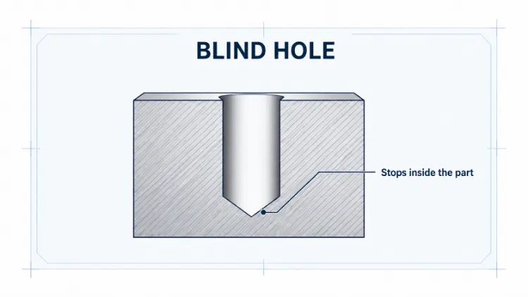
Was ist ein Sackloch?
Ein Sackloch wird bis zu einer vorgegebenen Tiefe hergestellt, ohne die gegenüberliegende Oberfläche zu durchbrechen. Es kann gebohrt, aufgebohrt, geräumt, gefräst oder mit einem Gewinde versehen werden. Die Wahl des Verfahrens hängt vom Durchmesser, der Tiefe, der Form des Lochbodens und der Toleranz ab.
Ein herkömmlicher Spiralbohrer hinterlässt am Boden eine konische Bohrspitze. Mit einem Flachbodenbohrer, einem Schaftfräser oder durch Ausbohren lässt sich ein flacherer Boden erzielen. Diese Möglichkeiten sind nützlich, wenn ein Bauteil am Boden der Bohrung anliegen muss.
Eine Blinddurchkontaktierung auf einer Leiterplatte ist etwas anderes. Sie verbindet eine äußere Leiterplattenlage mit einer oder mehreren inneren Lagen. Dieser Artikel befasst sich mit maschinell gefertigten Blindbohrungen in Metall- und Kunststoffteilen.
4 wichtige Tiefen von Sacklöchern
In Zeichnungen von Sacklöchern sollte die vorgesehene Tiefe eindeutig angegeben werden. Vier Maße werden häufig verwechselt:
- Tiefe über den gesamten Durchmesser: die Länge des zylindrischen Abschnitts bei dem angegebenen Durchmesser.
- Bohrspitzentiefe: die Gesamttiefe, einschließlich der konischen Bohrspitze.
- Gewindetiefe: die erforderliche Länge vollständiger, funktionsfähiger Gewinde.
- Bohrtiefe: die Gesamttiefe des Lochs vor dem Gewindeschneiden.
Die Gewindebohrtiefe ist in der Regel größer als die Gewindetiefe. Der zusätzliche Platz dient zur Aufnahme der Gewindefase, unvollständiger Gewindegänge und Späne. Werden diese Maße verwechselt, kann dies zu einem zu kurzen Gewinde oder zu einem Durchbohren führen.
Was ist das Symbol für ein Sackloch?
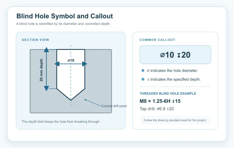
Es gibt kein eigenständiges universelles Symbol, das für sich genommen “Blindloch” bedeutet. In einer Zeichnung wird das Durchmessersymbol in der Regel mit einem Tiefensymbol oder einer schriftlichen Tiefenangabe kombiniert. Eine gängige Beschriftung lautet:
⌀10 ↧20
Dies steht für ein Loch mit einem Durchmesser von 10 mm und einer angegebenen Tiefe von 20 mm. Das Symbol ⌀ bezeichnet den Durchmesser. Das Symbol ↧ gibt die Tiefe an. In der geltenden Zeichnungsnorm sollte festgelegt sein, ob sich die Tiefe auf den Abschnitt mit vollem Durchmesser oder auf die Bohrspitze bezieht. Fügen Sie eine Anmerkung hinzu, wenn diese Unterscheidung Auswirkungen auf die Funktion hat.
Bei einem Blindloch mit Gewinde kann in der Zeichnung Folgendes angegeben sein: M8 × 1,25–6H ↧15. Die Bohrtiefe kann separat festgelegt werden, zum Beispiel GEWINDBOHRER ⌀6,8 ↧20. Dadurch wird verhindert, dass der Zerspaner die Gewindetiefe und die gesamte Bohrtiefe als denselben Wert betrachtet.
Sackloch vs. Durchgangsloch
Ein Durchgangsloch verläuft vollständig durch das Werkstück. Sein offenes Ende erleichtert oft den Spanabtransport, jedoch können am Austritt Grate oder Ausbrüche entstehen.
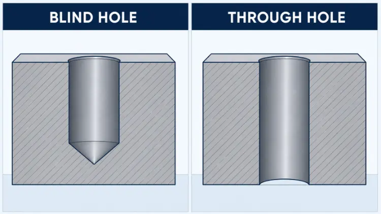
Ein Sackloch sorgt dafür, dass die gegenüberliegende Oberfläche unbeschädigt bleibt. Dabei müssen die Geometrie des Bohrungsbodens und die verbleibende Wandstärke genauer kontrolliert werden.
| Merkmal | Sackloch | Durchgangsbohrung |
|---|---|---|
| Abschlussbedingung | Haltestellen innerhalb des Teils | Lässt sich von beiden Seiten öffnen |
| Chip-Evakuierung | Die Chips werden durch den Eingang zurückgegeben | Chips können an beiden Enden austreten |
| Tiefensteuerung | Kritisch | In der Regel werden die Qualität beim Durchbruch und beim Austritt kontrolliert |
| Bodengeometrie | konisch, flach oder speziell geformt | Kein geschlossener Boden |
| Anzapfen | Erfordert Bodenfreiheit und Späneabführung nach oben | Es können Werkzeuge verwendet werden, die Späne nach vorne befördern |
| Häufige Risiken | Verklumpte Späne, übermäßige Hitze, beschädigte Werkzeuge und Durchbruch | Auslaufgrate, Ausbrüche und Kantenbeschädigungen |
Keine der beiden Ausführungen ist grundsätzlich günstiger oder genauer. Die Kosten hängen vom Material, dem Durchmesser, der Tiefe, der Toleranz und dem Prüfplan ab.
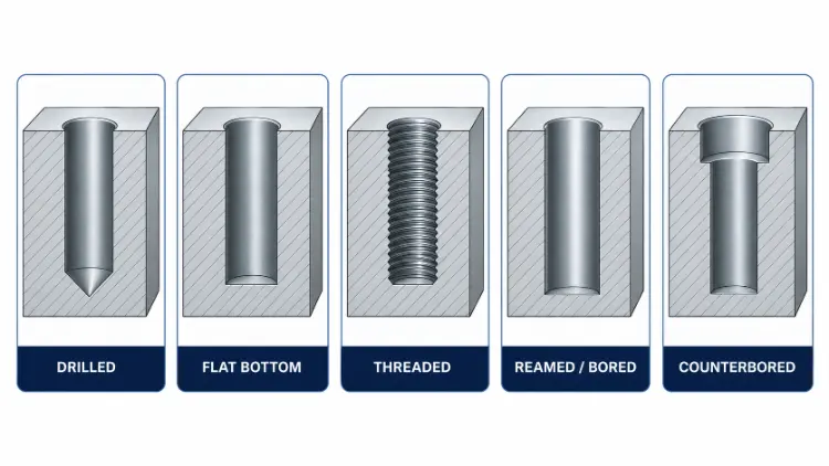
Gängige Arten von Sacklöchern
Standardmäßig gebohrte Sacklöcher
Diese Bohrungen werden mit einem Spiralbohrer hergestellt. Sie eignen sich für Fälle, in denen ein konischer Bohrungsboden akzeptabel ist.
Blindlöcher mit flachem Boden
Eine Bohrung mit flachem Boden bietet eine kontrollierte Auflagefläche. Dazu kann ein Flachbodenbohrer, eine Fräsmaschine oder eine Bohrmaschine verwendet werden. Die Aufspannung muss ausreichend stabil sein, um Vibrationen zu begrenzen.
Blindlöcher mit Gewinde
Gewindesacklöcher ermöglichen eine Befestigung von innen, ohne dass die gegenüberliegende Seite geöffnet werden muss. Unterhalb des gesamten Gewindes muss Platz für den Gewindeschneider und die Späne vorhanden sein.
Aufgebohrte oder aufgebohrte Sacklöcher
Durch Reiben und Bohren lassen sich Durchmesser, Rundheit, Lage oder Oberflächengüte verbessern. Mit einem Reibahle lässt sich kein quadratischer Boden fräsen, und es ist ein Mindestabstand zum Boden erforderlich. Beim Bohren lassen sich Lage und Durchmesser genauer einstellen.
Versenkte Sacklöcher
Eine Senkung bildet nahe dem Eintrittsbereich eine zylindrische Stufe. Sie kann dazu dienen, einen Schraubenkopf zu versenken oder eine Befestigungsfläche zu schaffen. Für ihren Durchmesser und ihre Tiefe sind separate Maßangaben erforderlich.
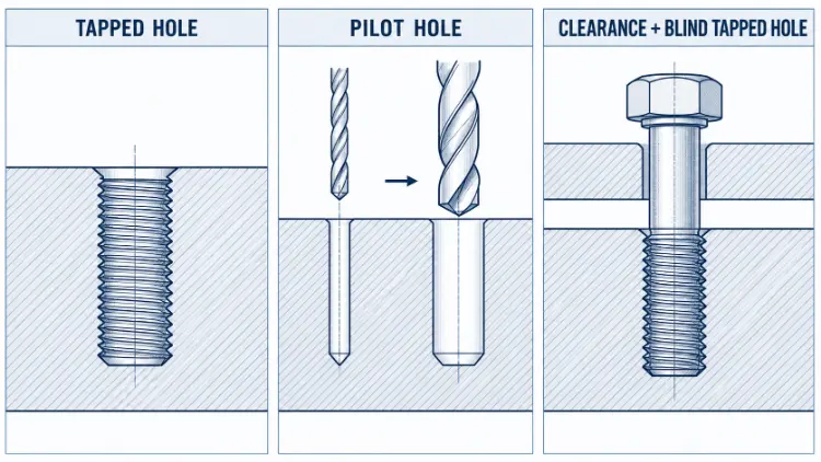
Inwiefern stehen Gewindebohrungen, Pilotbohrungen und Durchgangsbohrungen mit Sacklöchern in Zusammenhang?
Die Begriffe beschreiben verschiedene Merkmale oder Prozessschritte. Jeder davon kann in einer Blindlochbaugruppe vorkommen, aber keiner ist eine andere Bezeichnung für ein Blindloch.
Gewindebohrungen
Ein Gewindebohrloch weist ein Innengewinde auf. Es kann blind oder durchgehend sein. Ein blindes Gewindebohrloch benötigt unterhalb des vollständigen Gewindes zusätzliche Tiefe für den Gewindeschneider und die Späne.
Vorbohrungen
Ein Vorbohrloch ist ein kleineres Startloch, das zur Führung eines größeren Bohrers oder zur Verbesserung der Positionierung dient. Der Begriff kann sich auch auf ein Loch beziehen, das vor einem weiteren Arbeitsschritt gebohrt wird. Beim Gewindeschneiden lautet der präzisere Begriff „Gewindebohrloch“. Nicht jedes Sackloch erfordert ein separates Vorbohrloch.
Durchgangsbohrungen
Ein Durchgangsloch ist größer als der Schaft des Befestigungselements, sodass dieses ohne Gewindeverbindung hindurchgeführt werden kann. In der Regel handelt es sich dabei um ein Durchgangsloch im ersten Bauteil. Das Gegenstück kann ein Sackloch mit Gewinde aufweisen. Ein Durchgangsloch kann bei einer speziellen abgestuften oder vertieften Ausführung auch blind sein, wobei “Durchgangsloch” die Passform beschreibt, während “blind” den Endzustand bezeichnet.
Warum ein Sackloch verwenden?
Blindlöcher sind nützlich, wenn die gegenüberliegende Oberfläche unversehrt bleiben muss. Außerdem können sie dazu dienen, einen nahegelegenen Durchgang, Hohlraum oder eine Dichtfläche zu umgehen.
Zu den üblichen Gründen für eine solche Auslegung zählen:
- eine äußere oder funktionale Oberfläche intakt halten;
- das Anbringen einer Schraube, eines Stifts, eines Sensors oder eines Steckers von einer Seite aus;
- unter Umgehung eines Flüssigkeitskanals oder eines inneren Hohlraums;
- um eine Auslaufgrate an der gegenüberliegenden Seite zu vermeiden;
- Erstellung eines Positionierungs- oder Einpresselements mit kontrollierter Einbautiefe.
Diese Vorteile gelten nur unter bestimmten Voraussetzungen. Ein Sackloch macht ein Bauteil nicht automatisch fester oder leichter. Es garantiert keine Druckdichtheit. Der Bohrungsboden kann zu einer lokalen Spannungskonzentration führen. Festigkeit, Dichtheit und Ermüdungslebensdauer müssen unter Berücksichtigung der tatsächlichen Geometrie und Belastung geprüft werden.
Vor- und Nachteile der Gestaltung von Sacklöchern
Ein Sackloch kann Probleme hinsichtlich Zugänglichkeit, Optik und Montage lösen. Es bringt jedoch auch fertigungstechnische Einschränkungen mit sich, die vor der Freigabe der Zeichnung geprüft werden sollten.
| Vorteile | Benachteiligungen |
|---|---|
| Schont die gegenüberliegende Oberfläche und verhindert die Entstehung von Auslaufgraten | Erfordert eine genauere Kontrolle der Tiefe, der Bodenform und der verbleibenden Wandstärke |
| Ermöglicht eine verdeckte Befestigung und einseitige Montage | Erschwert den Spanabtransport und die Kühlung |
| Kann nahegelegene Durchgänge, Hohlräume und funktionsrelevante Oberflächen umgehen | Erfordert zusätzlichen Freiraum an der Unterseite zum Bohren und Gewindeschneiden |
| Ermöglicht die Anbringung von Elementen mit kontrollierter Einbautiefe, als Presspassung oder mit Gewinde | Kann Späne, Kühlmittel oder Luft einschließen und während der Montage zu einer Hydraulikblockade führen |
| Hält mehr Material zurück als ein gleichwertiges Durchgangsloch an derselben Stelle | Für tiefe Bohrungen oder Bohrungen mit engen Toleranzen sind unter Umständen Spezialwerkzeuge, zusätzliche Arbeitsschritte und umfangreichere Prüfungen erforderlich. |
| Entfernt eine direkte Öffnung durch das Bauteil | Garantiert keine Dichtheit und kann zu lokalen Spannungskonzentrationen führen |
Die richtige Wahl hängt von der Funktion, der Zugänglichkeit und dem Fertigungsrisiko ab. Wenn ein Durchgangsloch die Konstruktionsanforderungen erfüllt, kann es die Entnahme des Chips und die Prüfung vereinfachen. Muss die gegenüberliegende Oberfläche geschlossen bleiben, ist möglicherweise ein Sackloch die bessere Lösung.
Wie werden Sacklöcher bearbeitet?
1. Die Zeichnung prüfen
Der Zerspaner prüft Durchmesser, Lage, Tiefe, Bodenform und Restwandstärke. Bei Gewindebohrungen müssen die Gewindebohr- und Vollgewindetiefe separat ermittelt werden.
2. Das Werkstück einspannen Datum
Die Tiefengenauigkeit hängt von einer zuverlässigen Referenzfläche ab. Die Werkzeuglänge, der Rundlauf und die tatsächliche Oberseite müssen überprüft werden. Bei unebenen Oberflächen kann ein Plandrehen erforderlich sein.
3. Wählen Sie das Werkzeug und die Zerspanungsstrategie aus
Das kürzeste geeignete Werkzeug bietet in der Regel die beste Steifigkeit. Seine Geometrie und die Kühlmittelzufuhr müssen auf das Material abgestimmt sein.
Das Peck-Bohren kann bei einigen Bohrungen dazu beitragen, Späne zu brechen und zu entfernen. Es ist jedoch nicht immer die beste Methode. Moderne Bohrer mit Innenkühlung erzielen möglicherweise bei einem stabilen, kontinuierlichen Vorschub bessere Ergebnisse. Die Entscheidung sollte auf der Grundlage der Empfehlungen des Werkzeugherstellers und von Werkstattversuchen getroffen werden.
4. Auf eine kontrollierte Tiefe bohren
Das CNC-Programm muss die Geometrie der Bohrspitze und die Werkzeuglängenkorrektur berücksichtigen. Ein Verharren oder Reiben kann zu erhöhter Wärmeentwicklung und Kaltverfestigung führen.
5. Die erforderlichen Funktionen fertigstellen
Auf das Bohren kann das Ausbohren, Aufreiben, die Bearbeitung des flachen Bodens oder das Gewindeschneiden folgen. Für jeden Schritt sind ausreichend Spanraum und Freiraum für das Werkzeug erforderlich.
6. Das Loch reinigen und überprüfen
Späne und Kühlmittel können sich am Boden ansammeln. Reinigen Sie die Bohrung vor der Messung oder Montage und überprüfen Sie anschließend die Maße, die die Funktion bestimmen.
Verfahren zum Gewindeschneiden von Sacklöchern
Das Gewindeschneiden in Sacklöchern ist anspruchsvoller als das Gewindeschneiden in Durchgangsbohrungen. Die Späne können nicht auf der gegenüberliegenden Seite austreten. Wenn sie sich unterhalb des Gewindebohrers ansammeln, steigt das Drehmoment an, und das Werkzeug kann brechen.
Gewindebohrer mit spiralförmiger Schneide
Ein Gewindebohrer mit Spiralnut leitet die Späne in Richtung des Eintritts. Die Geometrie der Nut muss auf das Material und die Gewindetiefe abgestimmt sein.
Bodenhähne
Ein Bodengewindebohrer hat eine kurze Fase und schneidet vollständige Gewinde näher am Boden. Er benötigt dennoch Freiraum für unvollständige Gewindegänge und Späne.
Formgewindebohrer
Ein Formgewindebohrer verdrängt Material und erzeugt keine Späne. Er eignet sich für bestimmte duktile Werkstoffe. Der Durchmesser der Vorbohrung und die Schmierung müssen sorgfältig kontrolliert werden.
Gewindefräsen
Beim Gewindefräsen wird das Gewinde mittels Kreisinterpolation erzeugt. Diese Methode ermöglicht eine Größenanpassung und eine kontrollierte Spanabfuhr. Sie kann sich bei großen Gewinden oder kostspieligen Bauteilen als vorteilhaft erweisen.
Die beste Methode hängt vom Werkstoff, der Gewindegröße, der Gewindetiefe, der Stückzahl und den Maschinenkapazitäten ab. Es gibt keinen Gewindebohrer, der für jedes Sackloch gleichermaßen geeignet ist.

Richtlinien für die Auslegung von Sacklöchern
Eine gute Konstruktion verringert das Bearbeitungsrisiko und sorgt für eine zuverlässigere Prüfung.
- Legen Sie die Tiefenreferenz fest. Geben Sie an, ob es sich bei dem Maß um die Tiefe über den gesamten Durchmesser oder um die Tiefe bis zur Bohrspitze handelt.
- Gewinde- und Gewindebohrtiefen getrennt angeben. Gehen Sie nicht davon aus, dass der Hersteller den erforderlichen Untermaßspielraum ermittelt.
- Verwenden Sie nach Möglichkeit eine Standardbohrspitze. Ein flacher Boden ermöglicht den Einsatz eines weiteren Werkzeugs oder einen weiteren Arbeitsschritt.
- Vermeiden Sie unnötige Tiefe. Ein hohes Verhältnis von Tiefe zu Durchmesser verringert die Steifigkeit des Werkzeugs und erschwert die Spanabfuhr.
- Schützen Sie die verbleibende Wand. Überprüfen Sie den Abstand zur gegenüberliegenden Fläche, zu nahegelegenen Bohrungen, Kanälen und dünnen Abschnitten.
- Geben Sie ausschließlich Funktionstoleranzen an. Enge Toleranzen bei Durchmesser, Position und Oberflächenbeschaffenheit stellen höhere Anforderungen an den Fertigungsprozess und die Qualitätskontrolle.
- Stellen Sie den Zugriff auf das Tool bereit. Schrägbohrungen und versetzte Einlassöffnungen erfordern unter Umständen Spezialwerkzeuge oder zusätzliche Einrichtungsschritte.
- Betrachten wir eingeschlossene Flüssigkeit. Eine Schraube, die in ein geschlossenes Loch eingeführt wird, kann Öl, Kühlmittel oder Luft zusammenpressen. Dies kann zu einer hydraulischen Blockade oder einem falschen Anzugsmoment führen.
- Zugänge für Inspektionen planen. Ein Merkmal, das mit einer Sonde nicht erreicht werden kann, erfordert möglicherweise eine andere Messvorrichtung oder eine andere Konstruktion.
Materialspezifische Überlegungen
Die Bearbeitung von Sacklöchern hängt vom Werkstückmaterial ab.
| Material | Gemeinsames Anliegen | Bearbeitungsrichtung |
|---|---|---|
| Aluminium | Lange Späne, Aufbauschneide und Materialhaftung | Scharfe Geometrie, effektive Spanabfuhr und geeignete Schmierung einsetzen |
| Rostfreier Stahl | Kaltverfestigung, Wärme und Haftung | Sorgen Sie für einen gleichmäßigen Vorschub und vermeiden Sie Reibung oder unnötige Verweilzeiten |
| Titan | Hitzekonzentration, Werkzeugverschleiß und Rückfederung | Verwenden Sie eine stabile Aufspannung, kontrollierte Schnittbedingungen und ein wirksames Kühlmittel |
| Kohlenstoffstahl und legierter Stahl | Unterschiedliches Spanverhalten je nach Güteklasse und Härtegrad | Wählen Sie Werkzeuge für die angegebene Güteklasse und den angegebenen Wärmebehandlungszustand aus |
| Technische Kunststoffe | Schmelzen, Grate, elastische Rückstellung und feuchtigkeitsbedingte Bewegungen | Verwenden Sie scharfe Werkzeuge, regulieren Sie die Hitze und beachten Sie die Prüftemperatur |
Feste Schnittgeschwindigkeiten und Vorschübe sollten nicht für verschiedene Werkstoffe übernommen werden. Sie hängen von der Werkstoffsorte, der Härte, der Bohrungsgröße, der Bohrtiefe, der Werkzeuggeometrie und dem Zugang für das Kühlmittel ab.
Häufige Probleme bei Sacklöchern
| Problem | Wahrscheinliche Ursache | Praktische Lösung |
|---|---|---|
| Falsche Tiefe | Falsche Tiefenangabe, Werkzeugversatz oder Bezugspunkt | Die Bemaßung präzisieren und die Werkzeuglänge sowie die Position auf der Oberfläche überprüfen |
| Verpackte Chips | Mangelhafte Spanabfuhr oder -abführung | Passen Sie den Zyklus, die Werkzeuggeometrie, das Kühlmittel oder die Rückzugsstrategie an |
| Abgebrochener Bohrer oder Gewindebohrer | Übermäßiges Drehmoment, falsche Ausrichtung, Verschleiß oder unzureichender Freiraum nach unten | Überprüfen Sie die Standzeit, die Einrichtungssteifigkeit, den Spanraum und die Prozessbelastung |
| Raue Bohrlochwand | Spanabtrag, Rundlaufabweichung, Vibrationen oder Aufbauschneide | Verbesserung des Spanabtransports, des Werkzeugzustands und der Einrichtungsstabilität |
| Mangelhafte Verarbeitung am unteren Rand | Falsches Werkzeug, Rattern oder verdichtete Späne | Wenden Sie ein geeignetes Veredelungsverfahren an und reinigen Sie das Werkstück vor dem Endschnitt. |
| Unvollständige Gewindetiefe | Zu flaches Vorbohrloch oder zu große Gewindefase | Geben Sie die Gewinde- und Gewindebohrtiefen separat an |
| Zufälliger Durchbruch | Falsche Tiefenangabe oder unzureichende Restwandstärke | Überprüfung von Aufmaß, Werkzeugspitze und Wanddickenzugabe |
| Eingeschlossenes Kühlmittel | Unzureichende Reinigung oder beengte Montagebedingungen | Reinigen Sie die Bohrung und ziehen Sie, sofern es die Konstruktion zulässt, eine Entlastungsführung in Betracht. |
So überprüfen Sie ein Sackloch
Der Prüfplan sollte auf das Merkmal und die Toleranz abgestimmt sein.
- Mit einem Tiefenmessgerät oder einem Tiefenmikrometer lässt sich die zugängliche Bohrlochtiefe überprüfen.
- Mit Stifte, Stecklehren oder Bohrungslehren lässt sich der Durchmesser prüfen.
- Mit einer Gewindelehre wird das Funktionsgewinde überprüft.
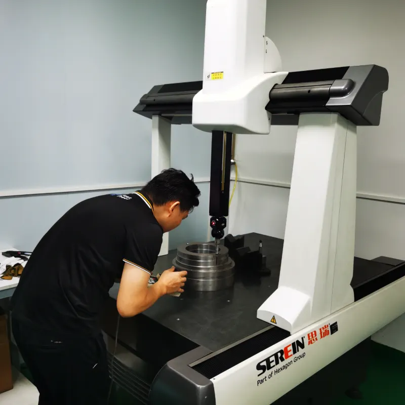
- Ein Koordinatenmessgerät (CMM) kann zugängliche Positionen, Durchmesser und ausgewählte Tiefenmerkmale messen.
- Mit einem Endoskop lassen sich Späne, Beschädigungen am Boden oder Oberflächenfehler erkennen.
- Ein Oberflächenprofilometer kann eine zugängliche Wand- oder Bodenoberfläche untersuchen.
Der Zugang für den Messtaster ist entscheidend. Ein Koordinatenmessgerät (CMM) kann nicht jedes Sackloch automatisch vermessen. Auch eine Sichtprüfung kann die Maßprüfung nicht ersetzen.
Gemeinsame Anwendungen
Blindlöcher kommen in Pumpen- und Ventilkörpern, Gehäusen für die Automobilindustrie, Maschinen, Robotergelenken und Halterungen vor. Außerdem dienen sie als Befestigungs- oder Ausrichtungselemente in elektronischen, medizinischen, optischen und Halbleitergeräten.
Mikrofluidik-Bauteile und Düsen können sehr kleine, geschlossene Strukturen aufweisen. Diese erfordern unter Umständen eine Laserbearbeitung, Mikro-EDM oder ein anderes Spezialverfahren.
Was ist der Zweck eines Sacklochs?
Ein Sackloch ermöglicht die Befestigung, Positionierung oder Gewindeanbringung im Inneren, ohne dass die gegenüberliegende Oberfläche geöffnet werden muss.
Was ist der Unterschied zwischen einem Sackloch und einem Durchgangsloch?
Ein Sackloch endet im Inneren des Bauteils. Ein Durchgangsloch verläuft vollständig durch das Bauteil hindurch und mündet auf beiden Seiten.
Wie sollte die Tiefe eines Sacklochs angegeben werden?
Geben Sie an, ob es sich bei dem Maß um die Tiefe über den vollen Durchmesser, die Bohrspitzentiefe oder die effektive Gewindetiefe handelt. Legen Sie außerdem die gewünschte Bodenform fest.
Wie groß sollte ein Loch vor dem Gewindeschneiden sein?
Die Größe des Vorbohrers hängt vom Gewinde, der Steigung, dem Werkstoff und dem Gewindebohrertyp ab. Bei metrischen Gewindebohrern ist der Nenndurchmesser abzüglich der Steigung ein guter Anhaltspunkt. Für ein M6 × 1-Gewinde wird üblicherweise eine Vorbohrung von 5,0 mm verwendet. Überprüfen Sie die endgültige Größe stets anhand der Tabelle des Gewindebohrerherstellers. Formgewindebohrer erfordern in der Regel eine größere Vorbohrung.
Wie markiert man Bohrstellen an Sacklöchern?
Für CNC-Bearbeitung, bestimmen Sie die Lage der Bohrung anhand der Zeichnungsbezugspunkte und der programmierten Koordinaten. Übernehmen Sie die Position nicht von einer anderen Bohrung. Um ein Muster für Gewindeblindbohrungen auf ein Gegenstück zu übertragen, setzen Sie Übertragungsschrauben ein und drücken Sie die Teile zusammen. Bei Bohrungen ohne Gewinde können geeignete Übertragungsstempel oder Zentrierstifte verwendet werden, sofern der Zugang dies zulässt.
Welchen Gewindebohrer verwendet man für ein Sackloch?
Ein Gewindebohrer mit Spiralnuten ist eine gängige Wahl, da er die Späne zum Einlauf hin abführt. Auch Gewindebohrer zum Ausbohren und Formen eignen sich für bestimmte Anwendungen. Bei größeren Gewinden oder kostspieligen Bauteilen kann das Gewindefräsen vorzuziehen sein. Wählen Sie die Methode anhand des Werkstoffs, der Gewindetiefe, des Spanraums und der Maschinenkapazität aus.
Wie lassen sich Späne aus einem Sackloch entfernen?
Verwenden Sie eine geeignete Werkzeuggeometrie, eine geeignete Kühlmittelzufuhr und einen validierten Bohrzyklus. Reinigen Sie die Bohrung vor der Prüfung oder Montage. Das Stanzbohren kann hilfreich sein, ist jedoch nicht für jedes Werkzeug oder Material erforderlich.
Benötigen Sie Hilfe bei der Überprüfung einer Sacklochkonstruktion?
Senden Sie Weldo Ihre Zeichnung mit Angaben zu Werkstoff, Lochdurchmesser, Tiefe, Gewinde, Toleranz und Stückzahl. Unser Team kann das Bauteil im Hinblick auf die Herstellbarkeit prüfen, bevor Angebot sowie die Produktionsplanung.