
Слепое отверстие заканчивается внутри детали, а не проходит сквозь нее. Его закрытое дно влияет на контроль глубины, удаление стружки и зазор инструмента. В данном руководстве рассмотрены основные типы отверстий, методы обработки, варианты нарезания резьбы и практические правила проектирования.
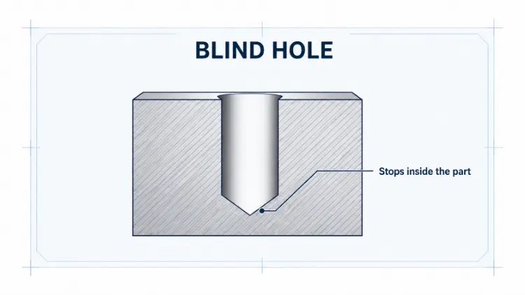
Что такое глухое отверстие?
Глухое отверстие проделывается на заданную глубину без пробивания противоположной поверхности. Оно может быть просверлено, расточено, расширено, выфрезеровано или нарезано резьбой. Выбор метода обработки зависит от диаметра, глубины, формы дна и допуска.
Стандартное спиральное сверло оставляет на дне отверстия коническое отверстие. Сверло с плоским дном, торцевая фреза или растачивание позволяют получить более плоское дно. Эти варианты полезны в тех случаях, когда деталь должна плотно прилегать к дну отверстия.
Слепое сквозное отверстие на печатной плате — это нечто иное. Оно соединяет внешний слой печатной платы с одним или несколькими внутренними слоями. В данной статье речь пойдет о механически обработанных слепых отверстиях в металлических и инженерных пластиковых деталях.
4 глубины глухих отверстий, которые нужно знать
На чертежах глухих отверстий должна быть чётко указана предполагаемая глубина. Часто путают четыре размера:
- Глубина по полному диаметру: длина цилиндрического участка с указанным диаметром.
- Глубина сверления: общая глубина, включая конический наконечник сверла.
- Глубина резьбы: требуемая длина целых, исправных резьб.
- Глубина сверления: общая глубина отверстия до нарезания резьбы.
Глубина сверления под метчик обычно превышает глубину резьбы. Дополнительное пространство необходимо для размещения фаски метчика, незавершенных витков резьбы и стружки. Путаница с этими размерами может привести к образованию укороченной резьбы или к пробиванию материала.
Какой символ используется для обозначения глухого отверстия?
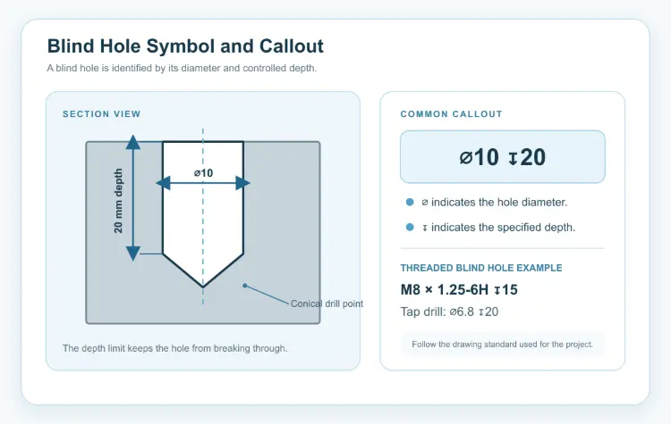
Отдельного универсального символа, который сам по себе обозначал бы “глухое отверстие”, не существует. На чертеже обычно сочетаются символ диаметра и символ глубины либо текстовая пометка с указанием глубины. Распространенная пометка:
⌀10 ↧20
Это обозначает отверстие диаметром 10 мм и указанной глубиной 20 мм. Символ ⌀ обозначает диаметр. Символ ↧ определяет глубину. В применимом стандарте на чертежи должно быть указано, относится ли глубина к участку полного диаметра или к вершине сверла. Добавьте примечание, если это различие влияет на функциональность.
В случае глухого резьбового отверстия в чертеже может быть указано M8 × 1,25–6H ↧15. Глубину сверления метчиком можно указать отдельно, например Сверло с резьбой ⌀6,8 ↧20. Это не позволяет оператору станка считать глубину резьбы и общую глубину сверления одинаковыми величинами.
Слепое отверстие и сквозное отверстие
Сквозное отверстие проходит насквозь через заготовку. Его открытый конец зачастую облегчает удаление стружки, однако на выходе могут образовываться заусенцы или отколы.
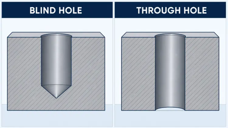
Глухое отверстие позволяет сохранить целостность противоположной поверхности. При его изготовлении требуется более тщательный контроль за геометрией дна и остаточной толщиной стенок.
| Характеристика | Слепое отверстие | Сквозное отверстие |
|---|---|---|
| Условие завершения | Остановки внутри детали | Открывается с обеих сторон |
| Эвакуация чипов | Чипы сдаются у входа | Чипы могут выпадать с любого конца |
| Регулировка глубины | Критический | Как правило, проводится контроль качества на этапах прорыва и выхода |
| Геометрия дна | Конические, плоские или специальной формы | Без закрытого дна |
| Отвод | Требуется зазор снизу и система удержания стружки, направленной вверх | Можно использовать инструменты, которые выталкивают стружку вперед |
| Распространённые риски | Забитые стружки, перегрев, поломка инструментов и прорыв | Заусенцы, отколы и повреждения кромок |
Ни одна из этих конструкций не является всегда более дешёвой или более точной. Стоимость зависит от материала, диаметра, глубины, допуска и плана контроля.
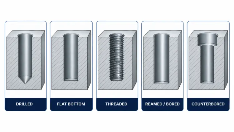
Распространенные типы глухих отверстий
Стандартные слепые отверстия с отверстиями
Эти отверстия просверливаются коническим сверлом. Их использование целесообразно в тех случаях, когда допустимо наличие конического дна.
Слепые отверстия с плоским дном
Отверстие с плоским дном обеспечивает контролируемую поверхность посадки. Для его изготовления можно использовать сверло с плоским дном, фрезерование или растачивание. Крепление должно быть достаточно жестким, чтобы свести к минимуму вибрацию.
Резьбовые глухие отверстия
Слепые отверстия с резьбой позволяют осуществлять внутреннее крепление без прорезания противоположной поверхности. Под всей длиной резьбы необходимо предусмотреть пространство для прохождения резьбы метчика и удаления стружки.
Расширенные или просверленные глухие отверстия
Расширительная обработка и растачивание позволяют улучшить диаметр, округлость, положение или качество поверхности. Расширитель не может вырезать квадратное дно и требует зазора в нижней части. Растачивание позволяет более точно регулировать положение и диаметр.
Сверло с углублением для глухих отверстий
Зенковка образует цилиндрический уступ вблизи входа. С её помощью можно утопить головку винта или создать монтажную поверхность. Её диаметр и глубина должны быть указаны отдельными пометками.
Как резьбовые, пилотные и проходные отверстия соотносятся с глухими отверстиями
Эти термины описывают различные характеристики или этапы технологического процесса. Каждый из них может встречаться в конструкции с глухим отверстием, однако ни один из них не является синонимом термина «глухое отверстие».
Резьбовые отверстия
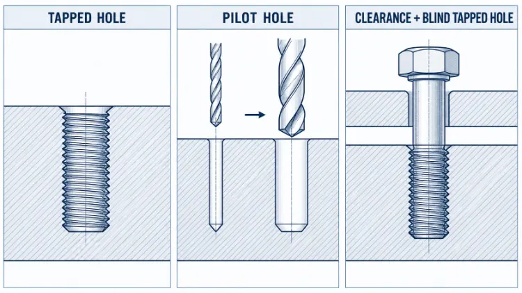
Резьбовое отверстие имеет внутреннюю резьбу. Оно может быть глухим или сквозным. Глухое резьбовое отверстие требует дополнительной глубины ниже окончания резьбы для прохождения резьбонарезного метчика и удаления стружки.
Пилотные отверстия
Пилотное отверстие — это начальное отверстие меньшего диаметра, которое используется для направления сверла большего диаметра или для уточнения местоположения. Этот термин также может обозначать отверстие, просверленное перед выполнением другой операции. При нарезании резьбы более точным термином является «отверстие для метчика». Не каждое глухое отверстие требует просверливания отдельного пилотного отверстия.
Проходные отверстия
Проходное отверстие имеет размеры, превышающие размеры штанги крепежного элемента, что позволяет крепежному элементу проходить через него без входа в резьбу. Обычно это сквозное отверстие в первом компоненте. Сопрягаемый компонент может иметь глухое резьбовое отверстие. Проходное отверстие может быть глухим при специальной ступенчатой или углублённой конструкции, однако термин “проходное” описывает посадку, а “глухое” — коневное состояние.
Зачем использовать глухое отверстие?
Глухие отверстия полезны в тех случаях, когда противоположная поверхность должна оставаться целой. Кроме того, они позволяют избежать пересечения с расположенным поблизости каналом, полостью или уплотнительной поверхностью.
К числу распространенных причин, связанных с проектированием, относятся:
- сохранение внешнего вида или рабочих свойств поверхности;
- установка винта, штифта, датчика или разъема с одной стороны;
- не затрагивая канал для прохождения жидкости или внутреннюю полость;
- предотвращение образования заусенца на противоположной поверхности;
- создание элемента с фиксированной глубиной посадки или с прессовой посадкой.
Эти преимущества носят условный характер. Глухое отверстие не делает деталь автоматически более прочной или лёгкой. Оно не гарантирует герметичность при давлении. Дно отверстия может создавать локальную концентрацию напряжений. Прочность, герметичность и усталостная долговечность должны проверяться с учётом фактической геометрии и нагрузки.
Преимущества и недостатки конструкции глухих отверстий
Глухое отверстие позволяет решить проблемы, связанные с доступом, внешним видом и сборкой. В то же время оно накладывает ограничения на производственный процесс, которые следует учесть до утверждения чертежа.
| Преимущества | Недостатки |
|---|---|
| Сохраняет целостность противоположной поверхности и предотвращает образование заусенцев на выходе | Требуется более тщательный контроль глубины, формы дна и остаточной толщины стенок |
| Поддерживает скрытое крепление и односторонний монтаж | Это затрудняет отвод стружки и охлаждение |
| Может обходить расположенные поблизости проходы, полости и рабочие поверхности | Требуется дополнительный зазор в нижней части для сверления и нарезания резьбы |
| Обеспечивает создание элементов с контролируемой глубиной расположения, с прессовой посадкой или резьбой | Может задерживать стружку, охлаждающую жидкость или воздух и вызывать гидравлическую блокировку во время сборки |
| Удерживает больше материала, чем аналогичное сквозное отверстие в том же месте | Для обработки глубоких отверстий или отверстий с узкими допусками могут потребоваться специальные инструменты, дополнительные операции и более тщательный контроль качества |
| Удаляет прямое отверстие, проходящее сквозь деталь | Не гарантирует герметичность и может привести к локальной концентрации напряжений |
Правильный выбор зависит от назначения, удобства доступа и производственных рисков. Если сквозное отверстие соответствует проектным требованиям, оно может упростить удаление стружки и контроль качества. Если противоположная поверхность должна оставаться закрытой, лучшим решением может стать глухое отверстие.
Как обрабатываются глухие отверстия?
1. Изучите чертеж
Станкстер проверяет диаметр, положение, глубину, форму дна и остаточную толщину стенок. Для резьбовых отверстий необходимо отдельно определять глубину нарезания резьбы и глубину полной резьбы.
2. Закрепить заготовку Базовая точка
Точность глубины зависит от наличия надёжной опорной поверхности. Необходимо проверить длину инструмента, биение и фактическое положение верхней поверхности. При наличии неровностей на поверхности может потребоваться торцевая обработка.
3. Выберите инструмент и стратегию управления стружкой
Как правило, наибольшую жесткость обеспечивает самый короткий подходящий инструмент. Его геометрия и система подачи охлаждающей жидкости должны соответствовать особенностям обрабатываемого материала.
В некоторых отверстиях бурение методом «пек» может способствовать измельчению и удалению стружки. Однако это не всегда является оптимальным методом. Современные сверла с внутренней подачей охлаждающей жидкости могут демонстрировать более высокую эффективность при стабильной непрерывной подаче. При принятии решения следует руководствоваться рекомендациями производителя инструмента и результатами цеховых испытаний.
4. Сверление до заданной глубины
В программе ЧПУ необходимо учитывать геометрию вершины сверла и компенсацию длины инструмента. Задержки или трение могут привести к повышению температуры и упрочнению материала.
5. Завершить реализацию обязательных функций
После просверливания отверстия может следовать растачивание, развертывание, обработка плоского дна или нарезание резьбы. На каждом этапе необходимо обеспечить достаточное пространство для удаления стружки и зазор для инструмента.
6. Очистите и осмотрите отверстие
На дне могут оставаться стружка и смазочно-охлаждающая жидкость. Перед проверкой калибрами или сборкой очистите отверстие, а затем проверьте размеры, определяющие работоспособность.
Методы нарезания резьбы в глухих отверстиях
Нарезание резьбы в глухих отверстиях более сложно, чем в сквозных. Стружка не может выходить с обратной стороны. Если она скапливается под метчиком, крутящий момент возрастает, и инструмент может сломаться.
Метчики со спиральной канавкой
Метчик со спиральными канавками отводит стружку к входу. Геометрия его канавок должна соответствовать материалу и глубине резьбы.
Донные краны
Метчик для доработки дна имеет короткую фаску и нарезает полную резьбу ближе к дну. При этом необходимо оставить зазор для неполных зубьев и стружки.
Формирующие метчики
Формирующий метчик вытесняет материал и не образует стружки. Он подходит для определенных пластичных материалов. Диаметр направляющего отверстия и смазка требуют тщательного контроля.
Фрезерование резьбы
При резьбофрезеровании для формирования резьбы используется круговая интерполяция. Данный метод позволяет регулировать размеры и контролировать удаление стружки. Он может оказаться полезным при обработке крупных резьб или дорогостоящих деталей.
Выбор оптимального метода зависит от материала, размера резьбы, глубины, количества и технических возможностей станка. Не существует единого типа метчика, подходящего для всех глухих отверстий.

Рекомендации по проектированию глухих отверстий
Грамотная конструкция снижает риски, связанные с механической обработкой, и повышает надежность контроля качества.
- Определите отсчет глубины. Укажите, является ли данный размер глубиной по полному диаметру или глубиной до вершины сверла.
- Отдельные значения глубины резьбы и глубины сверления. Не рассчитывайте, что производитель сам определит необходимый припуск на нижнюю часть.
- По возможности следует использовать стандартное сверло. Плоское дно позволяет добавить ещё один инструмент или операцию.
- Избегайте излишней глубины. Большое соотношение глубины к диаметру снижает жесткость инструмента и затрудняет удаление стружки.
- Защитите оставшуюся часть стены. Проверьте расстояние до противоположной поверхности, близлежащих отверстий, каналов и тонких участков.
- Укажите только функциональные допуски. Жесткие допуски по диаметру, положению и качеству поверхности повышают требования к технологическому процессу и контролю качества.
- Обеспечьте доступ к инструментам. Для просверливания наклонных отверстий и вырезов в входных отверстиях могут потребоваться специальные инструменты или дополнительная настройка оборудования.
- Рассмотрим запертую жидкость. Винт, входящий в закрытое отверстие, может сжать масло, охлаждающую жидкость или воздух. Это может привести к гидравлической блокировке или появлению ложного момента затяжки.
- Спланируйте доступ для проведения инспекции. Для элемента, к которому зонд не может подойти, может потребоваться другой измерительный прибор или иная конструкция.
Особенности, связанные с конкретными материалами
Обработка глухих отверстий зависит от материала заготовки.
| Материал | Общая проблема | Направление обработки |
|---|---|---|
| Алюминий | Длинные стружки, наплавленная кромка и прилипание материала | Используйте четкую геометрию, эффективный отвод стружки и подходящую смазку |
| Нержавеющая сталь | Упрочнение при деформации, нагрев и адгезия | Обеспечьте стабильную подачу и избегайте трения или излишней задержки |
| Титан | Концентрация тепла, износ инструмента и упругая деформация | Используйте жесткую конструкцию станка, контролируемые условия резания и эффективную смазочно-охлаждающую жидкость |
| Углеродистая и легированная сталь | Различия в поведении стружки в зависимости от сорта и степени твердости | Выберите инструмент для указанной марки стали и состояния термообработки |
| Инженерные пластмассы | Плавление, заусенцы, упругое восстановление и деформация под воздействием влаги | Используйте острые инструменты, контролируйте нагрев и учитывайте температуру проверки |
Не следует применять одинаковые значения скорости и подачи для разных материалов. Они зависят от марки стали, твёрдости, размера и глубины отверстия, геометрии инструмента и доступа охлаждающей жидкости.
Распространенные проблемы, связанные с глухими отверстиями
| Проблема | Вероятная причина | Практический ответ |
|---|---|---|
| Неправильная глубина | Неверное значение глубины, смещение инструмента или система отсчета | Уточните указания и проверьте длину инструмента и положение поверхности |
| Чипсы в упаковке | Неэффективное разрушение или удаление стружки | Отрегулируйте цикл, геометрию инструмента, подачу охлаждающей жидкости или схему выхода инструмента |
| Сломанное сверло или метчик | Превышение момента кручения, неправильная регулировка, износ или недостаточное пространство в нижней части | Проанализируйте ресурс инструмента, жесткость установки, пространство для удаления стружки и технологическую нагрузку |
| Неровная поверхность скважины | Переточка режущей кромки, биение, вибрация или наслоение | Улучшить отвод стружки, состояние инструмента и стабильность настроек |
| Некачественная отделка дна | Неподходящий инструмент, вибрация или уплотнение стружки | Примените подходящий метод отделки и очистите изделие перед окончательной резкой |
| Недостаточная глубина резьбы | Недостаточная глубина пилотного отверстия или чрезмерная фаска метчика | Укажите глубину резьбы и глубину сверления метчиком отдельно |
| Случайный прорыв | Неверная отметка глубины или недостаточная толщина оставшейся стенки | Проверить наслоение, положение режущей кромки инструмента и припуск на толщину стенки |
| Застрявшая охлаждающая жидкость | Недостаточная уборка или тесное рабочее пространство | Очистите отверстие и, если это допускает конструкция, предусмотрите обходной канал |
Как провести осмотр глухого отверстия
План контроля должен соответствовать характеристикам и допускам.
- С помощью глубиномер или микрометра глубины можно проверить глубину доступного отверстия.
- Проверку диаметра можно проводить с помощью штифтовых, втулочных или отверстиевых калибров.
- Калибр для резьбовых заглушек служит для проверки работоспособности внутренней резьбы.
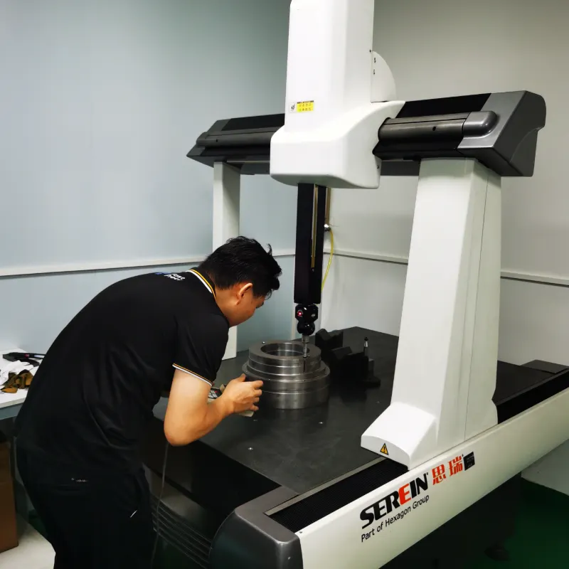
- Координатно-измерительная машина (КИМ) может измерять доступные положения, диаметры и заданные глубинные характеристики.
- С помощью бороскопа можно обнаружить стружку, повреждения дна или дефекты поверхности.
- Профилометр поверхности может оценивать доступную поверхность стенки или дна.
Важен доступ щупа. Координатно-измерительная машина (КИМ) не может автоматически измерить все элементы глухих отверстий. Визуальный осмотр также не может заменить проверку размеров.
Общие приложения
Глухие отверстия встречаются в корпусах насосов и клапанов, автомобильных корпусах, машиностроительных изделиях, шарнирах роботов и зажимных приспособлениях. Они также служат элементами крепления или центрирования в электронном, медицинском, оптическом и полупроводниковом оборудовании.
В микрофлюидных деталях и соплах могут применяться очень мелкие глухие элементы. Для их изготовления может потребоваться лазерная обработка, микроэлектроэрозионная обработка (микро-ЭДМ) или другой специализированный процесс.
Для чего нужен глухой отверстие?
Глухое отверстие служит для внутреннего крепления, фиксации или резьбового соединения без прорезания отверстия на противоположной поверхности.
В чём заключается разница между глухим отверстием и сквозным отверстием?
Глухое отверстие заканчивается внутри детали. Сквозное отверстие проходит через деталь насквозь и открывается с обеих сторон.
Как следует указывать глубину глухого отверстия?
Укажите, является ли данный размер глубиной по полному диаметру, глубиной до вершины сверла или эффективной глубиной резьбы. Также определите требуемую форму дна.
Какого размера должно быть отверстие перед нарезанием резьбы?
Размер направляющего отверстия зависит от резьбы, шага, материала и типа метчика. Для метрических режущих метчиков в качестве отправной точки удобно использовать номинальный диаметр за вычетом шага. Для резьбы M6 × 1 обычно используется направляющее отверстие диаметром 5,0 мм. Окончательный размер всегда следует уточнять по таблице производителя метчика. Формовые метчики, как правило, требуют более крупного направляющего отверстия.
Как разметить места сверления в глухих отверстиях?
Для Обработка на станках с ЧПУ, определите положение отверстия по базовым точкам чертежа и запрограммированным координатам. Не копируйте его положение с другого отверстия. Чтобы перенести схему резьбовых глухих отверстий на сопрягаемую деталь, установите переносные винты и сожмите детали друг с другом. Для отверстий без резьбы можно использовать подходящие переносные пуансоны или центрирующие штифты, если это позволяет доступ.
Какой метчик вы используете для глухого отверстия?
Метчик со спиральной канавкой часто выбирают из-за того, что он отводит стружку к входу. В определенных случаях также подходят метчики для прорезания дна и формирования резьбы. Для резьбы большого размера или дорогостоящих деталей предпочтительным может быть резьбофрезерование. Выбор метода зависит от материала, глубины резьбы, пространства для стружки и возможностей станка.
Как удалить стружку из глухого отверстия?
Используйте инструмент с подходящей геометрией, систему подачи охлаждающей жидкости и проверенный цикл сверления. Перед проверкой или сборкой очистите отверстие. Сверление методом «пек» может помочь, но оно не является обязательным для всех инструментов или материалов.
Нужна помощь в проверке проекта глухого отверстия?
Отправить Weldo ваш чертеж с указанием материала, диаметра отверстия, глубины, резьбы, допуска и количества. Наша команда может оценить технологичность данного элемента перед тем, как котировка и планирование производства.