
Shot peening is a mechanical surface-strengthening process that introduces residual compressive stress into the surface layer of a metal through controlled media impacts. It is primarily used to improve fatigue life, contact-fatigue resistance, resistance to stress-corrosion cracking, and reliability under cyclic loading.
For custom-parts buyers, shot peening should not be specified only by surface appearance or treatment time. Material condition, heat-treatment hardness, shot media, Almen intensity, coverage, masking, dimensional change, surface roughness, and inspection requirements all affect final performance, cost, and lead time.
This guide explains how shot peening works, when it should be used, which parts require special controls, how to define acceptance criteria, and how to evaluate a shot-peening supplier.
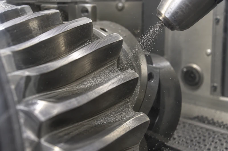
What Is Shot Peening and What Does It Do to Metal?
Shot peening propels spherical media, such as steel shot, conditioned cut-wire shot, glass beads, or ceramic beads, against a metal surface at controlled velocity.
Each impact creates a microscopic indentation and plastically stretches a small area of the surface. The underlying material restrains this deformation, producing a layer of residual compressive stress. External tensile stress must first overcome this compressive stress before the surface experiences effective tensile loading.
Properly processed shot-peened parts generally exhibit the following changes:
- Longer fatigue life: Residual compressive stress reduces the damaging effect of cyclic tensile loads. This is especially important at gear roots, spring surfaces, shaft-shoulder fillets, weld toes, and connecting-rod transitions.
- Improved contact-fatigue resistance: Proper shot peening can delay pitting and microcrack formation on gear teeth, splines, rolling-contact surfaces, and other cyclic-contact areas.
- Improved resistance to stress-corrosion cracking: Surface compressive stress reduces the tensile-stress component that drives stress-corrosion cracking. Shot peening does not create a corrosion barrier and cannot replace plating, painting, passivation, or corrosion-resistant material selection.
- A possible increase in surface microhardness: Work hardening can slightly increase the surface microhardness of some metals. It does not significantly increase bulk hardness, core strength, or tensile strength and cannot replace carburizing, quenching, or nitriding.
- Changed surface roughness: Media impacts create uniform microscopic indentations. These support compressive-stress development but can affect sealing, sliding, coating adhesion, and precision fits.
Shot peening can be applied selectively to fillets, hole edges, weld toes, gear roots, and other fatigue-sensitive areas without changing the entire part’s heat-treated microstructure.
The strengthening effect depends on material strength, surface hardness, media, intensity, coverage, and operating temperature. High temperatures, severe overloads, and long-term cyclic loading can relax part of the residual compressive stress. High-temperature components must therefore be qualified under representative service conditions.
Why Is Shot Peening Important for Fatigue-Critical Parts?
Fatigue cracks commonly begin at or near the surface. Machining marks, grinding scratches, corrosion pits, weld toes, and geometric transitions create localized stress concentrations. Repeated bending, torsion, vibration, or contact loading can initiate cracks at these locations.
Shot peening improves fatigue performance through three primary mechanisms:
- Residual compressive stress: It offsets part of the applied tensile stress and reduces the effective tensile-stress amplitude at the surface.
- Surface work hardening: In materials with sufficient strain-hardening capacity, media impacts increase surface dislocation density and resistance to localized plastic deformation.
- Resistance to crack opening and propagation: Cracks do not open easily within a compressive-stress field, so a higher cyclic load is required for continued growth.
These are the main benefits of shot peening for gears, springs, shafts, connecting rods, welded structures, landing gear, and other components exposed to repeated loading.
Shot peening cannot repair an existing crack. Parts must be inspected for cracks, grinding burns, welding defects, and material discontinuities before treatment.
Limitations of Shot Peening
Shot peening improves surface stress conditions, but it also introduces manufacturing risks that must be controlled.
- Surface roughness increases: Media-generated indentations can affect sealing, sliding friction, bearing fits, appearance, and subsequent coating performance.
- Dimensions can change: Thin-walled, slender, or asymmetrical parts can bend, warp, or lose roundness because of uneven surface deformation.
- Media can become embedded: Soft metals and porous components are susceptible to embedded media and require suitable media, reduced intensity, and thorough cleaning.
- Internal cavities can retain media: Blind holes and enclosed passages require verified cleaning and inspection methods.
- Existing defects remain present: Material delamination, cracks, lack of fusion, deep corrosion pits, and grinding burns cannot be repaired by shot peening.
- Process validation adds cost: Fatigue-critical and aerospace parts require documented intensity verification, coverage control, traceability, and inspection.
Shot peening should therefore be selected according to the part’s failure mode, geometry, material, manufacturing sequence, and service conditions.
Suitable Materials and Required Process Controls
| Категория материала | Suitability and control priorities |
|---|---|
| Carbon and low-alloy steels | Widely used for gears, shafts, pins, connecting rods, and springs. Media size and intensity must be matched to heat-treatment hardness and fatigue requirements. |
| Case-hardening steels | Suitable for gear roots and other high-stress areas. Excessive intensity can damage a thin hardened case, sharp edges, or finished ground surfaces. |
| Spring steels | Well suited to improving bending- and torsional-fatigue life in coil springs, leaf springs, and torsion bars. |
| Нержавеющие стали | Suitable for shot peening, but stainless-steel, ceramic, or glass media should be used to prevent free-iron contamination from carbon-steel media. |
| Алюминиевые сплавы | Suitable for aerospace structures and lightweight parts. Fine, low-density media and lower intensity are required to control indentation depth, distortion, and embedment. |
| Титановые сплавы | Suitable for aerospace and medical components. Media contamination, surface roughness, and impact intensity require strict control. |
| Nickel- and cobalt-based alloys | Suitable for high-temperature and high-cycle components. Qualification must account for residual-stress relaxation at elevated temperatures. |
| Магниевые сплавы | Suitable for controlled processing, but ferrous contamination, surface damage, dust collection, and fire safety require strict management. |
| Медь и медные сплавы | Their relatively soft surfaces are susceptible to deep indentation and media embedment. Fine media and low intensity are required. |
| Powder-metallurgy parts | Suitable only after pore structure, density, media retention, and functional requirements have been evaluated. |
| Additively manufactured metal parts | Shot peening can improve surface stress conditions but cannot eliminate internal porosity, lack of fusion, or other build defects. |
Ceramics, glass components, graphite, and most brittle nonmetallic materials are unsuitable for conventional metal shot-peening parameters. These materials lack the ductility required for stable surface plastic deformation and can crack, chip, or fracture under impact.
When Must a Part Not Be Shot Peened?
Existing Cracks
Surface cracks, quench cracks, grinding cracks, and welding cold cracks must be resolved before shot peening.
Residual compressive stress may temporarily reduce crack opening, but it does not restore material continuity. Shot peening cannot convert a rejectable crack into an acceptable structure.
Severe Material or Manufacturing Defects
Shot peening can improve the stress condition of a sound surface, but it cannot repair structural or metallurgical discontinuities.
- Forging laps or material delamination: These defects create unbonded interfaces. Media impacts cannot restore bonding and can promote crack growth from the defect edge.
- Weld lack of fusion or incomplete penetration: These defects reduce the effective load-bearing section of the weld. Surface compressive stress cannot repair the internal metallurgical discontinuity.
- Severe slag inclusions or concentrated porosity: These defects create internal stress concentrations that remain potential crack-initiation sites after peening.
- Through-connected casting porosity: Surface-connected pores can retain media, cleaning fluid, or corrosive substances while reducing sealing performance and fatigue strength.
- Lack of fusion in additively manufactured parts: Shot peening can modify the surface but cannot replace hot isostatic pressing, remelting, or defect removal.
- Severe grinding burns: Grinding burns can produce temper softening, rehardening layers, residual tensile stress, and microcracks. They require inspection and corrective action before peening.
- Extensive decarburization: Decarburization reduces surface hardness and fatigue strength. Shot peening cannot restore the lost carbon content or heat-treated microstructure.
- Deep corrosion pits: Corrosion pits reduce the effective cross-section and create a strong notch effect. Shot peening cannot restore lost material or eliminate cracks at the bottom of a pit.
Magnetic-particle testing, liquid-penetrant testing, ultrasonic testing, metallographic inspection, or industrial CT should be selected according to the material and defect type.
Enclosed Features That Cannot Be Cleaned
Deep blind holes, capillary passages, internal channels, and non-removable layered structures can retain media or fragments.
Residual shot can interfere with lubrication, sealing, cooling-fluid cleanliness, valve operation, and precision assembly. Nozzle access, media drainage, cleaning, and inspection must be confirmed before processing.
Surfaces with Existing Brittle or Precision Coatings
The following surfaces must not be shot peened unless the drawing or an approved process specifically permits it:
- Hard chromium plating: The coating is hard and brittle. Media impacts can produce network cracking, edge chipping, or delamination.
- Anodized coatings: Anodic films have a porous, ceramic-like structure and can fracture under repeated impact.
- PVD and CVD coatings: Plastic deformation of the substrate can crack or detach these thin, hard coatings.
- Thermal-spray coatings: Media impacts can crush the lamellar coating structure, expose pores, and weaken adhesion.
- Paint and organic coatings: Shot impacts can remove the coating, expose the substrate, and contaminate the media.
- Decorative plating: Thin nickel, decorative chromium, and similar coatings can lose their finish or develop dents and edge separation.
- Brittle electroless coatings: Hard electroless deposits are sensitive to substrate deformation and can develop microcracks or local delamination.
The normal sequence is to complete machining and heat treatment, perform shot peening, and then apply the final coating. Peening over a finished coating requires a separately qualified process.
Parts Requiring Special Qualification
The following parts are not automatically prohibited, but standard parameters for conventional steel parts must not be applied without validation:
- Thin-walled plates and tubes: One-sided or localized peening can cause bending, ovality, or warping. Symmetrical treatment, low intensity, dedicated support, and staged peening are required.
- Slender shafts and precision diaphragms: These parts are highly sensitive to residual-stress imbalance. Straightness, flatness, and free-state dimensions must be measured before and after processing.
- Porous sintered and powder-metallurgy parts: Open pores can retain fragments and dust. Peening can also close functional surface pores and affect oil retention, self-lubrication, or filtration.
- Nitrided parts: A hard and brittle compound layer can crack, chip, or delaminate under excessive impact. Intensity must be selected according to compound-layer condition and nitrided-case depth.
- Parts with borided or other brittle compound layers: Representative specimens and cross-sectional inspection are required to establish a safe process window.
- Sliding, sealing, and precision-fit surfaces: Peening changes roughness and can affect friction, lubrication, sealing, and fit. These surfaces should be masked or provided with an allowance for subsequent controlled finishing.
- Highly asymmetric parts: Uneven section thickness and one-sided treatment can produce unbalanced deformation. Fixturing and peening sequence must be validated.
Controlled Shot Peening: Almen Intensity and Coverage
Controlled shot peening uses validated media, Almen intensity, coverage, and automated movement parameters to produce repeatable residual compressive stress in specified areas.
Almen Intensity
Almen intensity uses standardized strips to measure the bending effect produced by the shot stream.
Common Almen strip types include:
- N-type: Used for low-intensity processes and delicate parts
- A-type: Used for most conventional shot-peening applications
- C-type: Used for higher intensities and heavier components
After peening, the strip develops an arc height. Multiple strips processed at different exposure times are used to establish a saturation curve.
Almen intensity is a standardized measure of process-impact capability. It is not the actual residual-stress value in the part and does not describe the full stress-depth profile.
Saturation Curve
The saturation point is established from the relationship between exposure time and Almen-strip arc height.
Under the commonly used criterion, saturation is reached when doubling the exposure time produces no more than the permitted additional increase in arc height. A single strip reading cannot replace a complete saturation-curve evaluation.
Coverage
Coverage represents the proportion of the specified surface affected by media-generated indentations.
- 100% coverage: The target area is covered by impact marks under the specified observation conditions.
- 200% coverage: The exposure time required to reach 100% coverage is doubled.
- 300% coverage: The exposure time is three times the time required to reach 100% coverage.
A requirement for 200% coverage does not mean that 200% of the physical surface area is covered.
Higher coverage reduces the risk of missed areas, but it also increases process time, roughness, and distortion risk. Coverage must be defined by the drawing, customer specification, or validated process.
Process Parameters and Media Selection
Parameters That Determine the Result
- Air pressure or centrifugal-wheel speed: Determines media velocity and directly affects impact energy and Almen intensity. Fluctuation produces inconsistent process results.
- Media flow rate: Determines the number of impacts per unit of time. Insufficient flow increases the time required to reach coverage, while excessive flow causes media collisions and reduces effective impact efficiency.
- Impact angle: Perpendicular impact delivers the highest normal energy. Oblique impact reduces effective intensity and can leave fillets, hole edges, and gear roots underprocessed.
- Nozzle distance: Excessive distance causes the shot stream to spread and lose intensity. Insufficient distance concentrates impacts and can produce local over-peening.
- Nozzle movement and path overlap: Travel speed and overlap determine exposure uniformity. Excessive speed causes incomplete coverage, while insufficient speed or excessive overlap creates local overexposure.
- Part rotational speed: Must be coordinated with nozzle movement and media flow to achieve uniform treatment of cylindrical and circumferential surfaces.
- Fixture shadowing: Fixtures, support points, and adjacent parts can block the media stream. Fixture design must maintain access to critical surfaces.
- Nozzle wear: Nozzle wear changes the outlet profile, media velocity, flow, and distribution. Inspection and replacement limits must be defined.
- Media-recovery and screening condition: The system must remove fragmented shot, undersized particles, dust, and foreign material. Poor media control reduces repeatability and increases contamination risk.
Media Selection
| Media | Main characteristics | Типичные применения |
|---|---|---|
| Cast steel shot | High density, high impact energy, and controlled cost | Gears, shafts, springs, and heavy steel parts |
| Conditioned cut-wire shot | Consistent shape and size with high durability | Repeatable controlled peening, gears, and aerospace parts |
| Stainless-steel shot | Reduces free-iron contamination from carbon-steel media | Stainless steels and cleanliness-sensitive components |
| Стеклянные бусины | Lower impact energy and low ferrous contamination | Aluminum alloys, thin-walled parts, and lower-intensity applications |
| Ceramic beads | Stable spherical shape, high wear resistance, and low fracture rate | Aerospace parts, titanium, aluminum, stainless steel, and high-cleanliness components |
Ceramic shot peening is commonly selected for aluminum, titanium, stainless steel, and cleanliness-sensitive parts because ceramic media retain their spherical shape and reduce ferrous contamination. Media size and intensity must still be validated against substrate hardness, dimensional stability, and surface-roughness limits.
Parts and Industries Using Shot Peening
| Промышленность | Typical parts and primary purpose |
|---|---|
| Аэрокосмическая промышленность | Landing gear, turbine disks, blades, shafts, springs, and structural connectors; improved fatigue reliability and resistance to stress-corrosion cracking |
| Автомобили и электромобили | Transmission gears, differential gears, connecting rods, crankshafts, drive shafts, and suspension springs; improved cyclic-load life |
| Construction and heavy machinery | Heavy-duty gears, pins, track components, and hydraulic-transmission parts; improved resistance to impact, bending, and contact fatigue |
| Энергетическое оборудование | Turbine parts, compressor components, shafts, and high-cycle load-bearing parts; reduced crack-initiation risk |
| Railway | Axles, springs, gears, and connectors; improved reliability under high-cycle loading |
| Marine and offshore engineering | Drive shafts, gears, fasteners, and welded structures; improved fatigue performance and stress-corrosion resistance |
| Industrial equipment | Dies, spindles, transmission components, and springs; longer service life and improved operating stability |
| Медицинские изделия | Titanium implants and precision metal components; controlled surface stress with strict contamination and cleanliness requirements |
Shot Peening for Aerospace
Shot peening for aerospace requires strict control of media material, Almen intensity, coverage, treatment boundaries, media contamination, and batch traceability.
Suppliers must retain saturation curves, equipment settings, program revisions, media-inspection records, and final inspection results according to the applicable customer, SAE, AMS, or OEM specification.
When Nadcap accreditation is required, the supplier’s approved scope must cover the actual process, equipment, material category, and component type. Accreditation alone does not automatically approve every process performed by the facility.
Gear Shot Peening
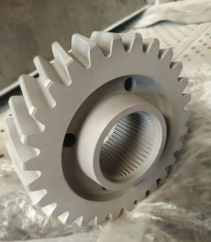
Gear shot peening primarily targets the tooth-root fillet and other high-bending-stress regions. Gear roots repeatedly experience bending stress during meshing and are common fatigue-crack initiation sites.
A typical sequence for carburized gears is:
- Rough and semi-finish gear machining
- Carburizing, quenching, and low-temperature tempering
- Снаряжение grinding or other finish machining
- Удаление заусенцев and surface inspection
- Shot peening of the tooth root and other specified areas
- Final cleaning and inspection
Шлифование allowance must be matched to the effective case depth. Excessive intensity can damage edges or increase roughness, while insufficient intensity cannot produce the required strengthening effect.
Shot Peening of Springs and Connecting Rods
Spring surfaces continuously experience bending or torsional stress. Shot peening introduces residual compressive stress into coil springs, leaf springs, and torsion bars, reducing fatigue-crack initiation under cyclic loading.
Spring processing must control coverage on inside curvatures, end transitions, and support areas. Part-to-part shadowing must be prevented through validated rotation and fixturing.
Connecting rods experience repeated tensile and compressive loads. Peening is commonly applied to the shank, fillet transitions, and other stress-concentration regions. Forged and powder-forged connecting rods must first be inspected for laps, decarburization, porosity, and machining defects.
Shot Peening of Welded Parts
Welded parts can be shot peened after weld quality has been confirmed. Treatment is commonly applied to the weld toe and nearby heat-affected-zone surface to reduce fatigue-crack initiation.
The correct sequence is:
- Complete all welding and repair welding
- Complete the specified post-weld heat treatment
- Remove spatter and dress sharp weld-toe transitions
- Perform visual and specified nondestructive testing
- Complete shot peening
- Inspect coverage, surface condition, and dimensions
- Apply final corrosion protection or coating
Shot peening cannot repair lack of fusion, incomplete penetration, slag inclusions, porosity, or weld cracks.
If welding is performed after shot peening, the welding thermal cycle will remove or redistribute the local residual compressive stress. The affected area must be reinspected and re-peened using an approved process.
Thin-walled welded parts also require distortion evaluation because welding residual stress and shot-induced plastic deformation can combine to produce warping.
Pre-Peening, Process, and Post-Peening Inspection
Pre-Peening Inspection
- Material and heat-treatment condition: Verify the material grade, heat-treatment batch, case condition, tempering condition, and specified hardness.
- Completion of critical machining: Confirm that machining of fatigue-critical surfaces has been completed and that subsequent operations will not remove the strengthened layer.
- Surface hardness: Confirm that hardness meets the drawing and process specification because it affects indentation depth, work hardening, and intensity selection.
- Cracks and grinding burns: Use magnetic-particle testing, liquid-penetrant testing, etching, or another specified method to identify defects before peening.
- Weld quality: Confirm completion of weld inspection, required weld-toe dressing, and any post-weld heat treatment.
- Surface cleanliness: Remove oil, loose oxide, rust, polishing compound, and machining residue that could obstruct impacts or contaminate the media.
- Treatment and masking boundaries: Confirm peened, transition, masked, and prohibited areas against the latest drawing.
- Initial dimensions and roughness: Record critical dimensions, flatness, straightness, roundness, and Ra or Rz values for post-process comparison.
Process-Control Records
The supplier should retain the following essential records:
- Applicable drawing, specification, and revision
- Media material, nominal size, condition, and screening result
- Almen strip type, saturation curve, and intensity range
- Coverage requirement, exposure time, equipment identification, and program revision
- Part batch, processing date, operator, and inspection results
A single Almen-strip reading does not replace a validated saturation curve. Process records must connect the completed part batch to the equipment and program used.
Post-Peening Inspection
- Coverage completeness: Confirm that all specified surfaces meet the coverage requirement, with particular attention to fillets, roots, hole edges, and fixture-adjacent areas.
- Masking effectiveness: Inspect threads, bearing seats, sealing surfaces, and other prohibited areas for unintended impacts.
- Шероховатость поверхности: Measure specified functional surfaces to confirm that indentation patterns have not compromised sealing, sliding, fitting, or coating requirements.
- Dimensions and distortion: Recheck flatness, straightness, roundness, and critical dimensions on precision, thin-walled, and slender parts.
- Surface integrity: Inspect for delamination, laps, abnormal indentations, microcracks, and edge damage. Perform magnetic-particle or liquid-penetrant reinspection where required.
- Media embedment and residue: Inspect soft-metal surfaces for embedded media and verify that blind holes and cavities are free from residual shot.
- Final cleanliness: Confirm that the part satisfies subsequent assembly, lubrication, coating, vacuum, or clean-environment requirements.
Can the Surface Be Touched After Shot Peening?
Bare-hand contact is not recommended after shot peening. Sweat contains moisture, salts, and oils that can contaminate the treated surface and increase the corrosion risk of carbon and low-alloy steels.
Fingerprints can also affect coating adhesion, bonding, vacuum service, and clean assembly. Operators should wear clean nitrile gloves and complete the required air blowing, cleaning, rust prevention, and sealed packaging.
A part that has passed final-cleanliness inspection should not be handled again without suitable protection.
Common Defects and Corrective Actions
| Проблема | Main cause | Corrective action |
|---|---|---|
| Incomplete coverage | Insufficient exposure, unsuitable nozzle path, or fixture shadowing | Adjust movement and exposure, improve accessibility, and revalidate coverage |
| Excessive roughness | Oversized media, excessive intensity, or fragmented shot | Reduce intensity, use finer media, and inspect the screening system |
| Thin-wall distortion | One-sided processing, excessive local exposure, or insufficient support | Use symmetrical peening, staged exposure, and dedicated fixtures |
| Media embedment | Soft substrate, fragmented media, or unsuitable media hardness | Select ceramic or glass media, reduce intensity, and improve cleaning |
| Intensity fluctuation | Unstable pressure, wheel speed, flow, media size, or nozzle condition | Calibrate equipment, screen the media, inspect the nozzle, and re-establish the saturation curve |
| Retained media | Enclosed geometry, blind holes, or insufficient cleaning access | Improve drainage, add controlled air blowing or cleaning, and verify with visual or borescope inspection |
Shot-Peening Cost and Cost-Control Methods
Cost Structure
Shot-peening cost can be represented as:
Total cost = Process preparation + Programming and fixturing + Masking + Machine time + Media consumption + Cleaning + Inspection and documentation + Packaging and logistics
Unit cost can be expressed as:
Unit cost = Fixed preparation cost ÷ Accepted quantity + Unit processing cost + Unit inspection cost
The main price drivers are:
- Part size, weight, and quantity
- Material and heat-treatment hardness
- Treatment area and geometric complexity
- Nozzle accessibility and fixturing difficulty
- Media material, size, and contamination requirements
- Almen intensity and coverage
- Masking complexity
- Thin-wall distortion control
- Roughness, cleanliness, and dimensional inspection
- First-article, traceability, and reporting requirements
- Dedicated fixture or process-development requirements
Why Unit Cost Changes with Quantity
For simple parts with stable batches and established parameters, shot peening is generally cost-effective. Programming, fixture setup, masking development, intensity verification, and first-article inspection are fixed or semi-fixed costs.
Increasing the quantity distributes these costs across more accepted parts. Prototype and low-volume orders have a higher unit cost because the same preparation and validation work is required for fewer parts.
Complex thin-walled parts, aerospace components, high-cleanliness parts, and projects requiring dedicated ceramic media cost more because of qualification, inspection, documentation, and contamination control.
How to Reduce Shot-Peening Costs
- Define treatment and masking boundaries clearly: Process only the fatigue-critical areas and avoid unnecessary masking.
- Group compatible parts: Combine parts with the same material, media, intensity, and coverage to reduce changeovers and repeated Almen verification.
- Improve nozzle accessibility: Avoid enclosed or obstructed features that require manual processing or complex fixtures.
- Use established specifications: Apply validated process windows instead of developing a new process for every order.
- Specify an appropriate inspection level: Retain complete records for aerospace and fatigue-critical parts without adding unnecessary aerospace-level documentation to ordinary industrial components.
- Optimize batch size and process sequence: Distribute fixture and first-article costs while defining heat treatment, grinding, peening, and coating order before production.
How to Select a Reliable Shot-Peening Supplier
A reliable supplier must be able to reproduce the same process result consistently, not simply operate shot-peening equipment.
The supplier evaluation should confirm:
- Experience with the same material, heat-treatment condition, and geometry
- Controlled shot-peening capability
- Ability to establish and retain Almen saturation curves
- Valid calibration of Almen gauges and inspection equipment
- Procedures for media screening, shape inspection, replacement, and contamination control
- Automated or repeatable control of nozzle movement, part rotation, and exposure time
- A defined method for coverage verification
- Experience controlling distortion in thin-walled, welded, and precision components
- Batch traceability covering equipment, program, media, and inspection results
- Applicable Nadcap scope for aerospace projects
- Defined procedures for nonconforming-product isolation, deviation approval, rework, and reinspection
What Information Should Be Included in an RFQ?
An effective RFQ should include:
- Part information: 2D drawing, 3D model, material grade, quantity, and annual demand
- Material condition: Heat treatment, case condition, surface hardness, and existing coating
- Treatment scope: Areas to be peened, transition zones, masked surfaces, and prohibited areas
- Process requirements: Applicable specification and revision, media requirement, Almen intensity, and coverage
- Quality limits: Surface roughness, critical dimensions, allowable distortion, and cleanliness
- Manufacturing sequence: Welding, heat treatment, grinding, machining, and coating performed before and after peening
- Delivery requirements: First-article approval, inspection reports, certificates, batch quantity, and target date
FAQ About Shot Peening
How Deep Does Shot Peening Affect Metal?
The affected depth depends on material strength, surface hardness, media size, media density, and impact intensity. The effect is concentrated in the near-surface region, and one fixed depth cannot represent every part.
For fatigue-critical components, the result should be confirmed through residual-stress depth profiling, microhardness gradients, or validated fatigue testing. Almen intensity alone cannot define the actual stress-depth profile in the part.
Can Cutting or Grinding Be Performed After Shot Peening?
Machining after shot peening removes part of the surface layer containing the residual compressive stress and reduces the strengthening effect. Fatigue-critical surfaces should normally be shot peened after final machining.
If controlled grinding is required after peening, the permitted stock-removal amount must be specified. Process validation must confirm that sufficient compressive stress remains after material removal.
Can a Shot-Peened Part Be Reworked?
Rework depends on the type of nonconformity. Incomplete coverage can be corrected through additional peening under an approved process.
Unintended peening, excessive roughness, distortion, cracked surface layers, or case damage cannot be repaired simply by peening the part again.
Reworked parts must be reinspected for intensity, coverage, dimensions, roughness, cleanliness, and surface integrity. Aerospace and fatigue-critical parts also require approval from the customer or responsible design authority.
How Is Shot-Peening Coverage Verified?
Coverage can be evaluated through controlled visual inspection, magnification, fluorescent tracers, or another method specified by the applicable standard.
Coverage verification must focus on difficult areas such as gear roots, fillets, recessed features, hole edges, and regions near fixtures. Surface appearance alone is not sufficient when the specification requires a documented verification method.
Does Shot Peening Change Part Dimensions?
Shot peening produces microscopic surface indentations and plastic extension. Rigid, symmetrical parts usually experience limited dimensional change, but thin-walled, slender, flat, or asymmetrical components can bend, warp, or lose roundness.
Critical dimensions and geometric tolerances should be recorded before and after processing. Fixtures, symmetrical treatment, lower intensity, and staged exposure can reduce distortion.
Заключение
Shot peening introduces controlled residual compressive stress into a metal surface to improve fatigue reliability, contact-fatigue resistance, and resistance to stress-driven crack initiation. It is widely used for gears, springs, connecting rods, shafts, welded structures, and aerospace load-bearing parts.
It is not ordinary abrasive cleaning and cannot repair cracks, material delamination, weld lack of fusion, severe porosity, or other structural defects.
A successful shot-peening project requires coordinated control of material condition, upstream manufacturing quality, media, Almen intensity, coverage, equipment movement, masking, dimensional change, шероховатость поверхности, and final cleanliness.
Buyers should define these requirements in drawings and technical agreements and select a supplier capable of providing saturation curves, media management, repeatable program control, batch traceability, and complete inspection records.